Installation manual – Vanos seal kit
The following information is provided for reference purposes only and should be used at your own risk
In no event shall Vanos-BMW.com or its members be liable for incidental, consequential, or special loss or damages of any kind however caused.
Introduction
“Vanos” is BMW’s name for its variable valve timing units. Vanos units take on various shapes and design according to car year and model (engine model). The vanos discussed here is BMW part # 11-36-1-748-036 (M50TU, US S50) and 11-36-1-748-819 (M52, S52). It’s a single vanos, meaning only the intake valve timing is varied. This vanos unit is part of BMW 6-cylinder engines M50TU, M52, US S50, S52. These engines were incorporated into a wide range of car models during years 1993-1999. They are found in the 3-series E36 93-97, 5-series E34 93-95 / E39 96-98, 7-series E38 95-98, Z3 Roadster 2.8 E36 96-98, EU Z3 Coupe 2.8 E36 96-98, US M3 E36 94-99, US Z3 M E36 98-99.
This vanos, like most vanos designs, can develop a rattle. The vanos rattle is caused by wear in the variable valve timing helical (slanted) gears. These gears are found on the camshaft, camshaft sprocket, and splined shaft which attaches to the vanos. The helical gear wear allows the camshaft to have lash movements that engage the splined shaft axially. At certain RPMs these movements resonate and engage axial play (free space) and cause associated components to hit and rattle. The axial play that facilitates the rattle is found on the helical gears and the vanos piston bearing. Replacing the helical gear components is expensive and the gears will wear again and the rattle will return. Removing the vanos piston bearing axial play significantly reduces the rattle to the point where it’s barely heard or not heard at all in the passenger compartment. Performance cams like the cams on the M3 or aftermarket performance cams (Schrick/Sunbelt) create stronger camshaft lash forces and thus are more susceptible to causing a rattle.
Vanos-BMW.com provides a vanos rattle repair kit which has a replacement component for the vanos piston bearing to remove the bearing axial play. Associate special tools are also provided to facilitate the repair.
Below is a more detailed explanation of the rattle cause and solution.
Technical background
To understand the cause of the vanos rattle some understanding of the BMW variable valve timing system is needed.
Variable valve timing is the modifying of the engine valve opening/closing timing dynamically. BMW’s variable valve timing implements a time shift (phase shift) scheme. The camshaft cam is not modified, thus all the characteristics of the opening and closing of the valve remain the same. What changes is the time when the valve opening/closing occurs relative to the crankshaft timing. The camshaft relative rotational position to the crankshaft is modified (shifted). Advancing (clockwise) the camshaft advances (earlier) the valve timing (opening/closing) relative to the crankshaft. Retarding (counter clockwise) the camshaft retards (later) the valve timing (opening/closing) relative to the crankshaft.
Helical (slanted) gears are utilized to physically implement this mechanism. Due to their nature, helical gears require a rotation to insert onto each other. This characteristic of helical gears is utilized to implement the relative rotation of the camshaft to the crankshaft dynamically while the engine is running.
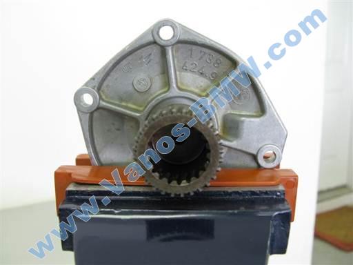
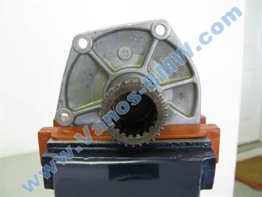
The camshaft and camshaft sprocket are not mounted directly to each other. The sprocket has a hole at its middle that’s larger than the camshaft end. Opposing slant helical gears are mounted at the sprocket hole and camshaft end. There is an independent splined shaft with a cup and helical gears on the inside and outside of the cup walls. The splined shaft cup inner helical gears match the camshaft helical gears and the splined shaft cup outer helical gears match the sprocket helical gears. The splined shaft cup is inserted onto and mates with the camshaft and sprocket helical gears. Thus the splined shaft connects the camshaft and sprocket. Inserting and withdrawing the splined shaft axially in/out of the camshaft and sprocket requires the rotation of a component due to the helical gears. The sprocket rotation is fixed by the timing chain. The splined shaft can’t rotate due to the opposing helical gear slants on its cup inside and outside. Thus it’s the camshaft that rotates when the splined shaft is manipulated axially.
Inserting the splined shaft axially onto the camshaft and sprocket causes the camshaft to advance (rotate clockwise) and cause advanced (earlier) timing.
Withdrawing the splined shaft axially from the camshaft and sprocket causes the camshaft to retard (rotate counter clockwise) and cause retarded (later) timing.
The vanos is a hydraulic actuator. Its function is to dynamically position the splined shaft axially to cause camshaft advance or retard rotation which enacts variable valve timing.
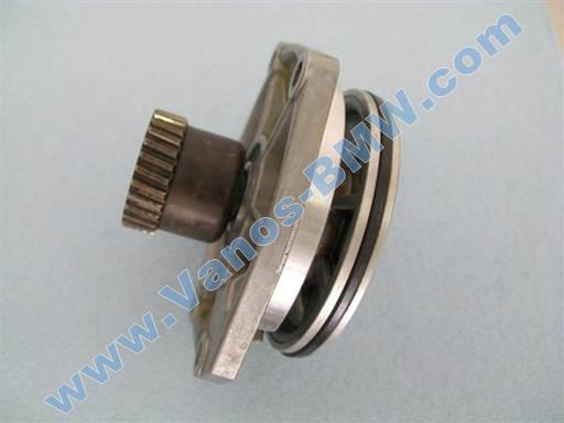
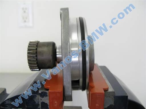
The vanos utilizes two cylinders and a piston. There is an oil chamber at the fore and aft of the piston. Controlling the oil pressure in the two oil chambers manipulates the axial position of the piston. Seals on the piston allow the piston to reciprocate axially along the cylinder walls while maintaining a tight oil seal on the two oil chamber. The splined shaft is mounted to the vanos piston. Thus manipulating the axial position of the piston also manipulates the axial position of the splined shaft. The piston has a bearing at its center. The splined shaft is mounted to this bearing. The piston bearing allows the splined shaft to rotate with the camshaft and sprocket while not rotating the piston.
Cause of rattle
Due to the nature of helical gears, not only does the axial positioning of the splined shaft cause the rotation of the camshaft, but also reciprocally the rotation of the camshaft causes the axial positioning of the splined shaft.
Over time and use the helical gears on the camshaft, sprocket, and splined shaft develop wear along the gear spline side contact surfaces. This wear creates excessive play between the helical gears. This causes excessive play in the fit of the splined shaft to the camshaft and sprocket. This manifests in axial play between the splined shaft and camshaft and sprocket.
As the camshaft rotates the cam nose rolls onto the valve seat and compresses the valve spring to open the valve and rolls off the valve seat and decompresses the valve spring to close the valve. The resistance force of the valve spring compression creates an opposing force to the forward rotation of the camshaft. The recoiling force of the valve spring decompression creates an additive force to the forward rotation of the camshaft.
Due to the splined shaft axial play, as the cam compresses the valve spring the camshaft will slightly retard in relative rotation to the crankshaft and as the cam decompresses the valve spring the camshaft will slightly advance in relative rotation to the crankshaft. These movements of the camshaft are due to camshaft least resistance path of movement. Due to the splined shaft axial play there is less resistance to the camshaft retarding than compressing the spring and less resistance to the camshaft advancing than containing the decompressing spring. These movements manifest into camshaft lashes which engage the splined shaft axially. The greater the helical gear wear the greater the splined shaft axial play the stronger the camshaft lashes.
At certain engine RPMs these camshaft movements resonate. This causes stronger camshaft lashes which cause more powerful engagements of the splined shaft axially. This causes strong axial movements of the splined shaft. Any axial play in the splined shaft vicinity is engaged and can cause a rattle.
There are two locations of axial play. The helical gears themselves have axial play that’s engaged and rattles and the vanos piston bearing has axial play that’s engaged and rattles.
Testing has been performed to assess and attempt to reduce the rattling. The vanos piston bearing radial play was modified and the results indicated little to no change in the rattling. The vanos piston bearing axial play was increased and this resulted in a proportional increase in the rattling. The vanos piston bearing axial play was decreased and this resulted in a proportional decrease in rattling.
The testing results show that removing the vanos piston bearing axial play significantly reduces the rattling.
Some owners have had the dealership replace their helical gears (splined shaft, camshaft, sprocket) and this resolved all the rattle. These owners eventually developed the rattle again and to the same level as before. This is due to the new helical gears wearing and creating the splined shaft axial play.
Engines with higher lift (performance) cams are more susceptible to having a vanos rattle, and the rattle is likely to be worse. The higher lift cams compress the valve springs further and thus cause higher spring forces. This causes stronger camshaft lashes which engage the splined shaft and axial play components harder.
This affects M3 cars and cars with aftermarket performance cams (Schrick/Sunbelt).
Rattle solution
As noted above removing the vanos piston bearing axial play significantly reduces the rattle. Also replacing the helical gear components (splined shaft, camshaft, sprocket) is expensive and the helical gears will wear again. Thus removing the vanos piston axial play is a practical approach to addressing the rattle problem. Furthermore, per bearing specification and consultation with bearings companies, there should be no bearing axial play and a notable axial pre-load (tightness) should be present.
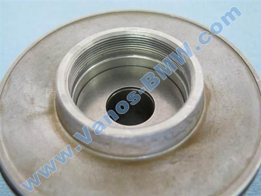
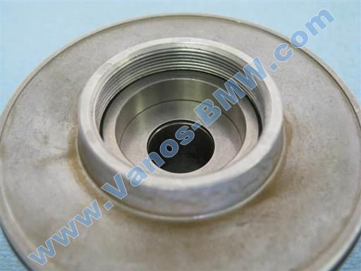
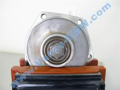
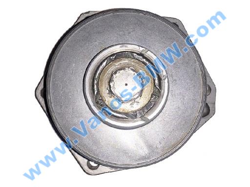
The vanos piston bearing is made of a thick washer and two thrust (roller) bearings. The washer if mounted to the splined shaft and the two thrust bearings sandwich the washer facilitating the washer to rotate at camshaft speed. The washer and two thrust bearings are incased in a ring and two ring outer washers. The complete bearing is housed inside a piston cavity and is closed off with a piston bolt/cap.
Removing the bearing axial play requires modifying or replacing at least one bearing component. The thrust bearings are a standard part and are manufactured to tight tolerances. It’s not feasible to modify or replace them. The ring and center washer are non standard parts and are manufactured to loose tolerances. The ring height can be reduced or the center washer height can be increased to remove the bearing axial play. The ring has been found to have a large height variation and the washer has been found to have a smaller height variation. Due to these findings, it’s more effective to replace the ring. A bearing adjustment can be made at installation to address any minor axial fit variation.
The bearing ring and center washer were assessed by a metallurgical consulting firm. The parts were assessed for their material makeup, hardness including micro depth hardness, manufacturing process and finish.
As a solution to the vanos rattle problem a replacement vanos piston bearing ring is manufactured to the same specification as the original bearing ring but with a shorter height and a very tight height tolerance. The other ring dimensions are also manufactured to tight tolerances.
The bearing ring is a difficult and expensive component to manufacture. It’s made from a special bearing steel and hardened to a high hardness. All its surfaces are ground. This technique allows for machining hard parts to a high dimensional tolerance and a polished surface.
The single vanos rattle repair kit includes one replacement vanos piston bearing ring.
Repair techniques
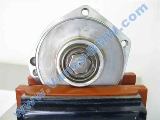
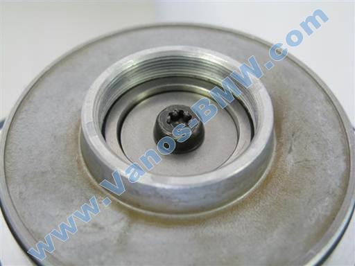
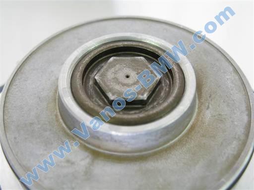
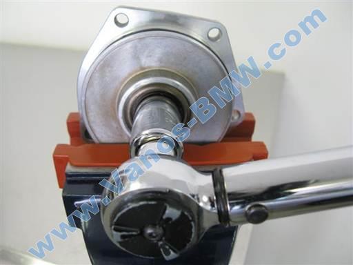
To replace the piston bearing ring the piston bolt/cap that retains the bearing must be removed. This is difficult due to the need to counter hold the piston to open the bolt/cap and the bolt/cap head being only 3mm high.
The piston has fins that allow for counter holding the piston to open the bolt/cap. But manufacturing a special tool for this purpose and providing it for a one time use is cost prohibitive. A vice can be used to counter hold the piston. A standard vise would damage the soft aluminum piston. Common aluminum and rubber coated aluminum vise jaw liners would also risk damaging the piston. Softer nylon vise jaw liners have been tested and found to hold the piston effectively without the risk of damaging it. Soft vise jaw liners are provided as an associate tool for the repair. The liners can also be useful for other delicate component work.
A standard socket has chamfers (bevels) at the socket opening that widen the opening to facilitate guiding the socket onto a bolt/nut head. Due to the piston bolt/cap head being 3mm high, a standard socket will grab the bolt/cap head with the opening chamfers. This has been found to cause the socket to slip and round the bolt/cap head corners. Machining off the socket opening chamfers allows the socket to have a tighter fit and improve the grab of the bolt/cap head. This prevents the socket from slipping off the bolt/cap head.
A socket machined to remove the opening chamfers is provided as an associate tool for the repair.
It has been found that first year model vanos units can have a 17mm or 18mm piston bolt/cap head, while the remainder model years vanos units always have an 18mm piston bolt/cap head. Thus for first year, 93, build cars both 17mm and 18mm sockets should be acquired for the repair.
17mm and 18mm sockets are provided as associate tools for the repair.
Symptoms
Vanos rattle at a certain RPM range, often 1800-2200 RPM. Rattle can also occur at idle.
This vanos is manufactured with a loose piston bearing. Thus all vanos units can rattle. For the vanos to rattle a resonance needs to be achieved in the camshaft lash and associate parts movements. Some car models are more susceptible to achieving this resonance and rattle than others.
Models susceptible to experiencing vanos rattle:
3-series E36 all models
5-series E34 all models
Z3 all models.
This list will be updates as more data is collected.
Note: All models can and have experienced the vanos rattle.
Repair Procedure
The following is a single vanos piston bearing rattle repair procedure.
This repair should be performed with the single vanos seals repair. The rattle repair should be performed before the new vanos seals are installed.
Single Vanos Seals Procedure
If the car is a pre March 95 build E36 320i/325i/Euro 328i or E34 520i/525i, then the intake sprocket diaphragm spring retrofit repair should also be performed.
Single Vanos Diaphragm Spring Procedure
Repair time: .5 hours mechanic, 1+ hours DIY.
Parts, Tools, and Shop Supplies
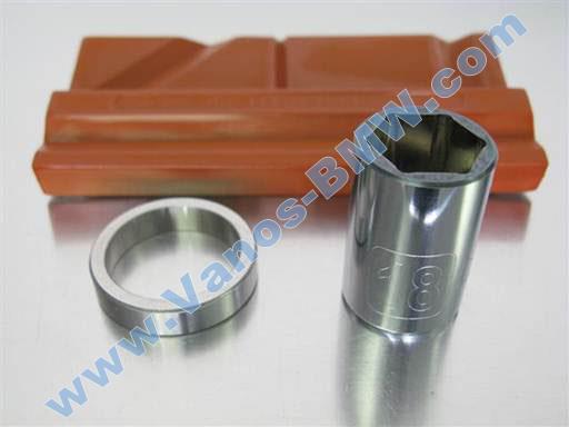
Single vanos rattle repair kit https://vanos-bmw.com/products.html, 18mm socket – 1/2” drive
Note: If car model year is 93 (first year of single vanos), vanos piston bolt/cap can be 17mm or 18mm, thus also acquire 17mm socket – 1/2” drive
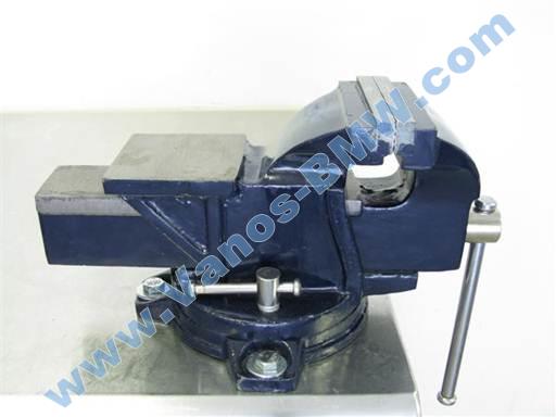
4”, or larger, swivel vise (Harbor Freight, 4” at store $45)
Note: Vise must be mounted for use.
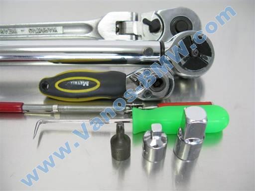
1/2″ long-arm ratchet, 1/4″ ratchet, 3/8″ torque wrench w/ reverse function (8 Nm [6 ft-lb], 40 Nm [30 ft-lb])
Magnet pickup, 90 degree pick tool
T30 torx bit socket 1/4″, 3/8” to 1/4″ socket adapter, 3/8” to 1/2″ socket adapter
Not shown: Heat gun (or alternate heating device)
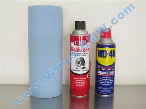
Paper towels, brake cleaner, oil spray
~400 grade sandpaper (not shown)
Repair
Repair is performed once vanos is removed from engine and vanos cylinder cover is removed. Refer to single vanos repair procedure, Single Vanos Procedure
Replace vanos piston seals after this procedure.
If vanos piston bolt/cap is 17mm, replace all references in procedure for 18mm to 17mm.
Removal of piston bearing
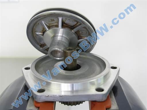
Clean vanos piston apparatus; piston, cover, splined shaft (brake cleaner & towels).
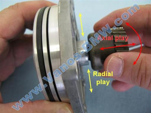
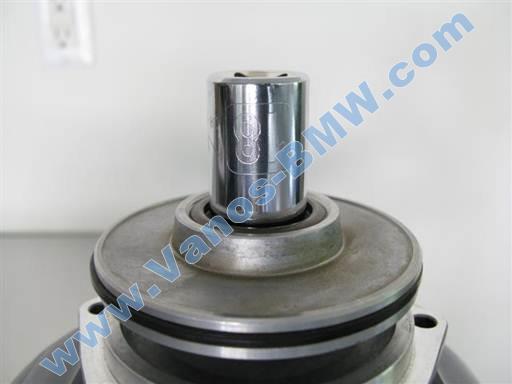
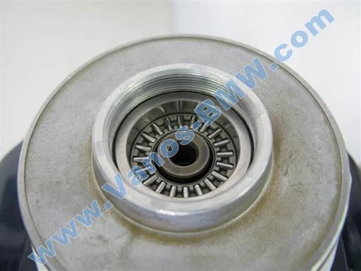
Inspect piston bearing axial play.
Hold piston and tilt (rock) splined shaft to each side to note bearing axial play (free space).
Axial play can also be checked by repeated insertion and withdrawal of splined shaft in/out of piston.
Note: Radial play, side to side movement, is normal and necessary. This should not be confused with axial play, in/out movement.
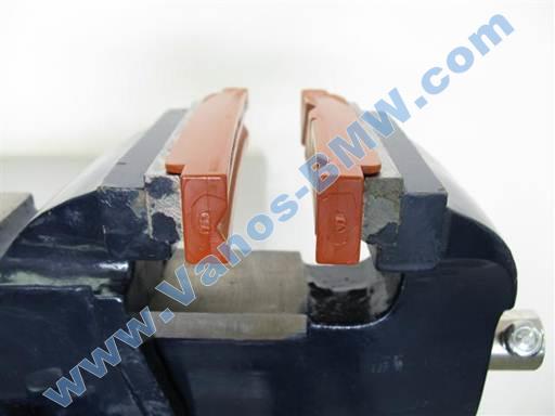
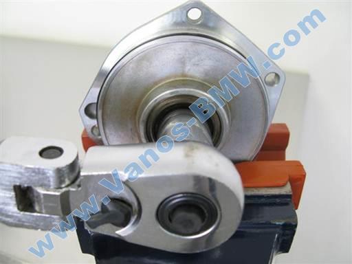
Attach soft vise jaw liners to vise jaws.
Place liner with horizontal V notch on vise inner jaw (picture left).
Place liner with vertical V notch and slanted V notch on vise outer jaw (picture right).
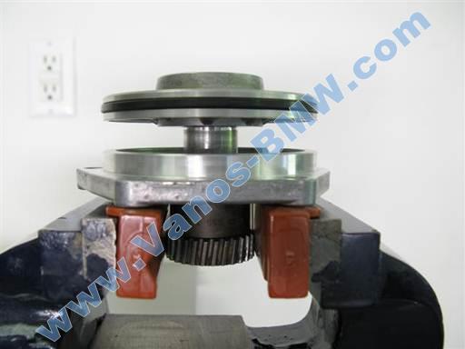
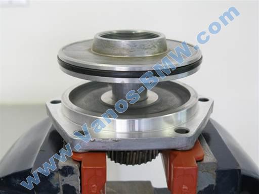
Open vise jaws as far as necessary to insert vanos piston and cover vertically (see next picture).
Press piston and cover together.
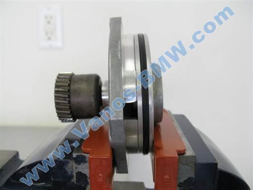
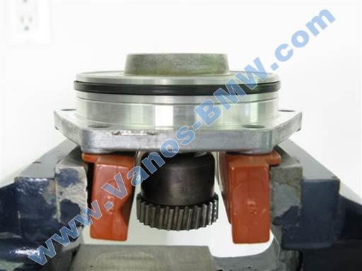
Insert piston apparatus in vise vertically with piston at vise outer jaw.
Rest piston center rim on jaw liner at center and lightly tighten vise to hold piston apparatus.
Note: Cover bolt holes have a raised surface surrounding them.
Slightly loosen vise and rotate cover to orient cover flat surface at vise jaw right side (picture).
Rotate cover to rest cover flat surface bolt hole rise on jaw liner right side (picture).
With this orientation, cover left side bolt hole will be located at liner horizontal V notch.
Note: Above cover orientation will cause cover right side bolt hole rise and cover left side bolt hole rise to be counter held by vise jaw liner and prevent cover from rotating when loosening piston bolt/cap.
Strongly tighten vise.
Note: Vise jaw liners are soft and will not damage piston and cover surfaces.
Caution: Do not clamp on piston apparatus without use of soft (nylon) vise jaw liners. Other types of jaw liners, including aluminum and rubber coated aluminum, can damage piston apparatus.
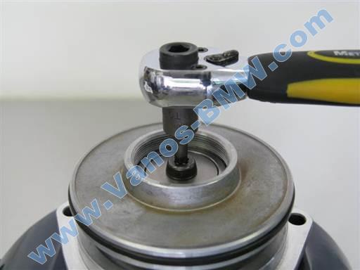
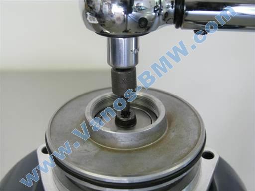
Loosen (break seize) piston bolt/cap (18mm modified socket 1/2” / 1/2” long-arm ratchet).
Hold in tool at bolt/cap (hand). Bolt/cap head is short and tool can dislodge.
If piston or cover rotate in vise jaws reposition piston apparatus per above instructions and strongly tighten vise.
If bolt/cap difficult to loosen apply heat to bolt/cap thread area (heat gun or alternate heating device)
Note: Do not further loosen piston bolt/cap at this time.
Once piston bolt/cap loosens (seize breaks), loosen vise and remove piston apparatus from vise.
Insert splined shaft vertically in vise and tighten vise jaws onto splined shaft.
Note: Specific position of splined shaft in vise is not significant.
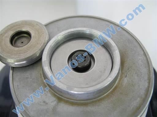
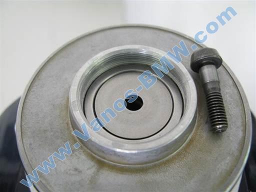
Remove piston bolt/cap (18mm modified socket 1/2” / hand).
Remove bearing top washer (magnet pickup).
Note: Washer is often bound to bolt/cap with oil and comes off with bolt/cap.
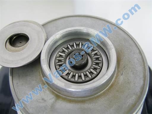
Remove bearing top thrust (roller) bearing (magnet pickup).
Remove bearing / splined shaft mounting bolt; left hand thread (T30 torx bit socket 1/4″ / 1/4″ ratchet).
Caution: Bearing/splined shaft mounting bolt is left hand thread. Turn clockwise to remove.
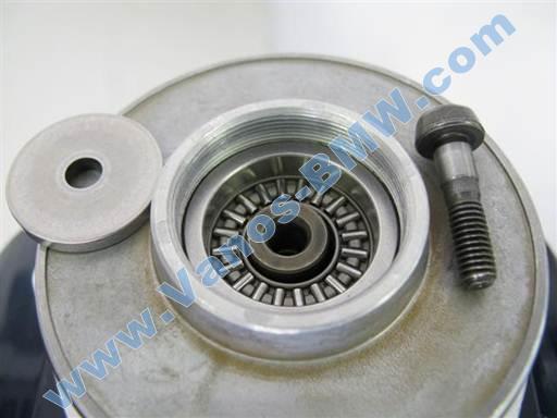
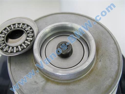
Remove bearing center washer (magnet pickup).
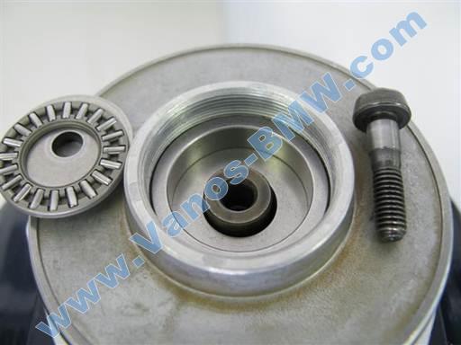
Remove bearing bottom thrust (roller) bearing (magnet pickup).
Remove piston from cover and splined shaft.
Hold down cover and pull up and rotate piston to remove from cover and splined shaft.
Place piston on table top.
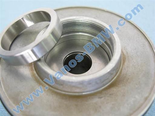
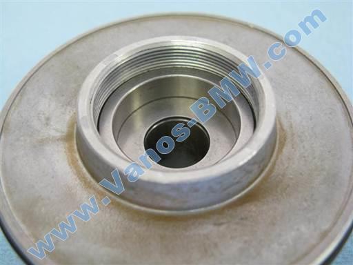
Remove bearing outer ring.
Clean bearing ring while still mounted in piston (brake cleaner & towels).
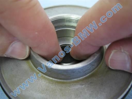
Insert right and left index fingers into bearing ring. Press against ring inner right and left walls and wiggle and pull ring out of piston.
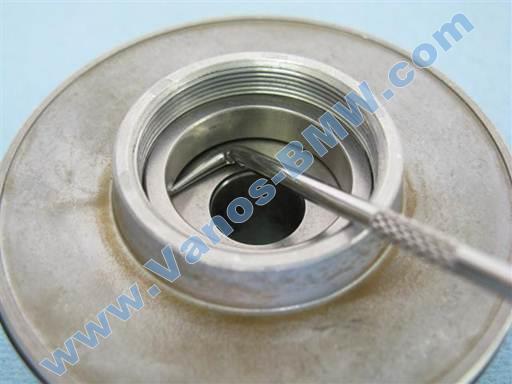
If ring is stuck, place pick tip between ring inner bottom and bottom washer and pry ring to break ring/washer seize (90 degree pick).
If ring tilts and binds in piston, press ring down to fully mount at bottom of piston and repeat removal attempt. If necessary, hit ring down to break bind and fully mount at bottom of piston (90 degree pick handle butt).
Set aside bearing ring as it will not be reinstalled.
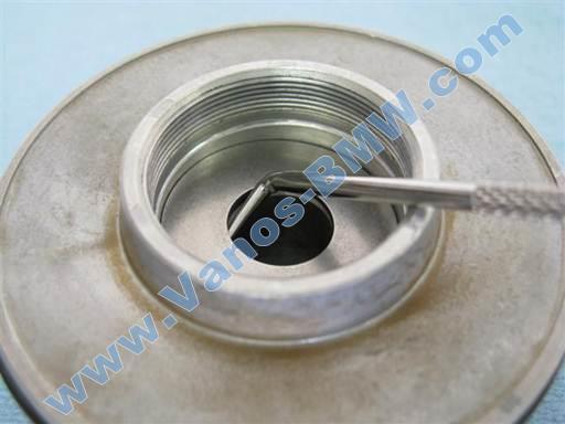
Remove bearing bottom washer.
Place pick tip between washer inner bottom and piston and pry washer out (90 degree pick).
Note: Washer is difficult to perceive until removed.
Cleaning of parts
Clean bearing parts (brake cleaner & towels).
Note: It is important bearing parts are thoroughly cleaned. This is needed to properly assess new bearing axial fit.
Clean piston bearing cavity and bolt/cap (brake cleaner & towels).
Installation of piston bearing
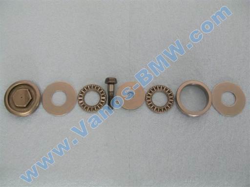
Bearing parts installation sequence from right to left.
Bearing parts from left to right: Bolt/cap, top washer, top thrust bearing, bolt, center washer, bottom thrust bearing, ring, bottom washer.
Insert bearing bottom washer in piston (fingers).
Note: Piston bearing top and bottom washers are interchangeable. Also washer faces are same thus washer can be inserted in either orientation.
Manipulate washer side to side while slightly pressing down to fully insert (fingers).
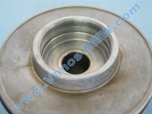
Insert new bearing outer ring in piston (fingers).
Note: New ring is marked “BS” on outer perimeter.
Initially insert ring in piston.
Insert right and left index fingers into ring. Press fingers against ring inner right and left walls and manipulate ring side to side while slightly pressing down to facilitate ring full insertion.
Rotate piston 90 degrees and repeat ring insertion to verify full insertion.
Note: Ring should fully mate with bottom washer (picture).
Remount piston onto cover and splined shaft.
Insert piston onto splined shaft.
Hold down cover and press and rotate piston into cover.
Insert bearing bottom thrust (roller) bearing in piston bearing ring.
Note: Piston bearing top and bottom thrust bearings are interchangeable. Also thrust bearing faces are functionally same thus thrust bearing can be inserted in either orientation.
Insert bearing center washer in piston bearing ring.
Note: Center washer faces are same thus washer can be inserted in either orientation.
Install bearing / splined shaft mounting bolt; left hand thread (T30 torx bit socket 1/4″ / 1/4″ ratchet).
Fully tighten, 8 Nm (6 ft-lb); left hand thread (T30 torx bit socket 1/4” / 3/8” torque wrench & 3/8” to 1/4″ socket adapter).
Caution: Do not over tighten bolt. 8 Nm (6 ft-lb) is slight torque.
Hold piton and loosen vise jaws.
Lower piston and cover and rest them on top of vise jaws.
Note: Splined shaft will suspend from piston and bearing center washer will drop down some into bearing ring (pictures).
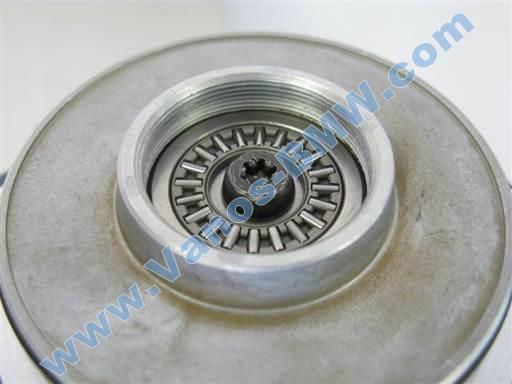
Insert bearing top thrust (roller) bearing in piston bearing ring.
Note: Thrust bearing faces are functionally same thus thrust bearing can be inserted in either orientation.
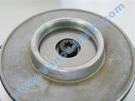
Insert bearing top washer on top of piston bearing ring.
Note: Washer faces are same thus washer can be inserted in either orientation.
Manipulate washer side to side while slightly pressing down to fully insert (fingers).
Install piston bolt/cap.
Counter hold piston and tighten bolt/cap (18mm modified socket 1/2” / hand).
Only hand tighten bolt/cap.

Loosen vise jaws and remove piston apparatus.
Open vise jaws as far as necessary to insert piston and cover vertically (see next picture).
Press piston and cover together.
Insert piston apparatus in vise vertically with piston at vise outer jaw.
Rest piston center rim on jaw liner at center and lightly tighten vise to hold piston apparatus.
Note: Cover bolt holes have a raised surface surrounding them.
Slightly loosen vise and rotate cover to orient cover flat surface at vise jaw right side (picture).
Rotate cover to rest cover left side bolt hole rise on jaw liner left side (picture).
With this orientation, cover right side bolt hole will be located at liner horizontal V notch.
Note: Above cover orientation will cause cover left side bolt hole rise and cover right side bolt hole rise to be counter held by vise jaw liner and prevent cover from rotating when tightening piston bolt/cap.
Strongly tighten vise.
Note: Vise jaw liners are soft and will not damage piston and cover surfaces.
Caution: Do not clamp on piston apparatus without use of soft (nylon) vise jaw liners. Other types of jaw liners, including aluminum and rubber coated aluminum, can damage piston apparatus.
Fully tighten piston bolt/cap, 40 Nm (30 ft-lb) (18mm modified socket 1/2” / 3/8” torque wrench & 3/8” to 1/2″ socket adapter).
Hold in tool at bolt/cap (hand). Bolt/cap head is short and tool can dislodge.
If piston or cover rotate in vise jaws reposition piston apparatus per above instructions and strongly tighten vise.
Once piston bolt/cap fully tightens, loosen vise jaws and remove piston apparatus from vise.
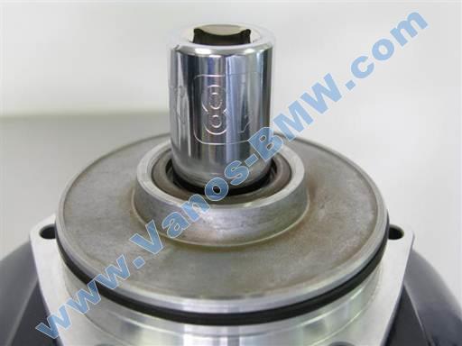
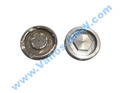
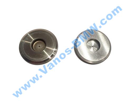
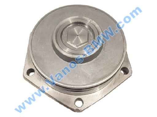
Sometimes piston nut is tightened so hard that when loosening can rip her face.
We produce new vanos piston nut to replace the damaged one. In the photo the old (damaged nut) and the new.
Inspection and adjustment of piston bearing
Inspect piston bearing axial play.
Hold piston and rotate splined shaft to note resistance to rotation.
Hold piston and tilt (rock) splined shaft to each side to note bearing axial play (free space).
Note: Axial fit cannot be properly assessed until piston bolt/cap is fully tightened.
Note: Radial play, side to side movement, is normal and necessary. This should not be confused with axial play, in/out movement.
If splined shaft binds and cannot be rotated then axial fit it too tight and loosening adjustment is needed.
If splined shaft has any tilt movement then axial play is present and tightening adjustment is needed.
Any level of resistance (pre-load) in splined shaft rotation indicates no axial play and is considered an optimal fit.
Note: M3 cars and cars with aftermarket performance cams (Schrick) must have no bearing axial play and bearing should have resistance to rotation (pre-load) to achieve optimal results.
Bearing loosening adjustment.
If splined shaft binds and cannot be rotated then axial fit it too tight and loosening adjustment is needed.
Disassemble piston bearing per above procedure.
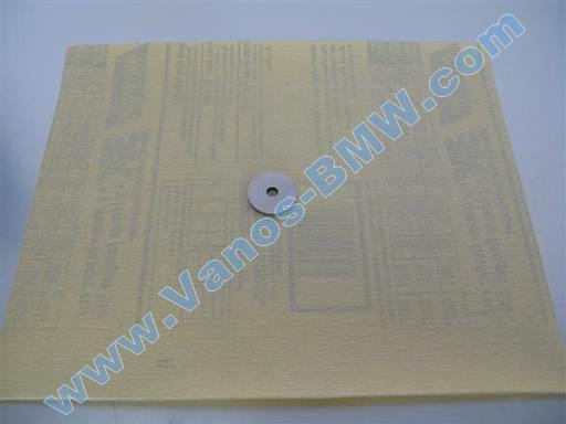
Place sandpaper (~400 grade) on flat table top. Place bearing center washer on sandpaper.
Slide washer side to side on sandpaper ~6” back and forth while moderately pressing washer on sandpaper. Perform sanding for 10 seconds.
Rotate washer 90 degrees and repeat sanding process.
Flip washer to opposite side and repeat above sanding procedure; 10 seconds sanding, rotate 90 degrees, 10 seconds sanding.
Clean washer (brake cleaner & towels).
Reassemble piston bearing per above procedure and reassess bearing axial fit.
Note: Washer is made from hardened steel and does not easily wear. Sanding procedure will remove ~.005mm washer height. Washer might need max .015mm height adjustment.
Bearing tightening adjustment.
If splined shaft has any tilt movement then axial play is present and tightening adjustment is needed.
Disassemble piston bearing per above procedure.
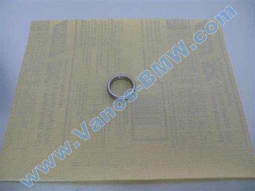
Place sandpaper (~400 grade) on flat table top. Place bearing ring on sandpaper.
Slide ring side to side on sandpaper ~6” back and forth while moderately pressing ring on sandpaper. Perform sanding for 10 seconds.
Rotate ring 90 degrees and repeat sanding process.
Flip ring to opposite side and repeat above sanding procedure; 10 seconds sanding, rotate 90 degrees, 10 seconds sanding.
Clean ring (brake cleaner & towels).
Reassemble piston bearing per above procedure and reassess bearing axial fit.
Note: Ring is made from hardened steel and does not easily wear. Sanding procedure will remove ~.005mm ring height. Ring might need max .015mm height adjustment.
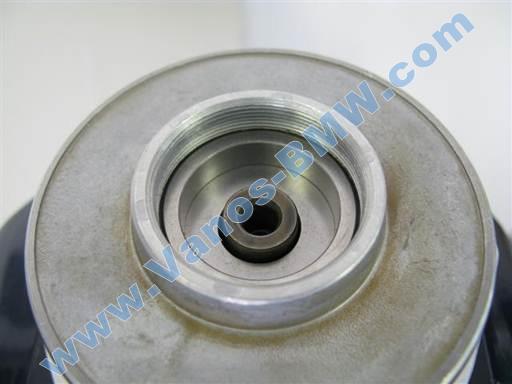
Once piston bearing fit is assessed and adjustment is performed if needed, spray oil into piston bearing (oil spray).
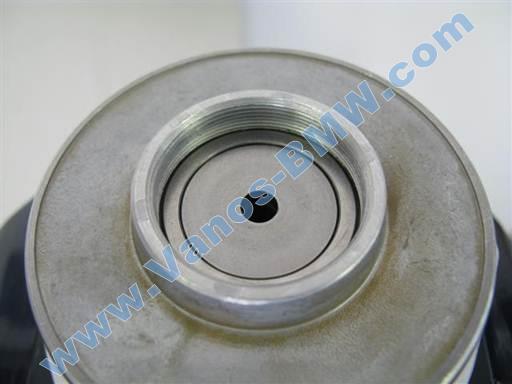
Center hole in piston bolt/cap facilitates access for oil spray.
Rotate splined shaft to distribute oil in bearing.