In no event shall Vanos-BMW.com or its members be liable for incidental, consequential, or special loss or damages of any kind however caused.
Introduction
“Vanos” is BMW’s name for its variable valve timing units. Vanos units take on various shapes and design according to car year and model (engine model). The vanos discussed here is BMW part # 11-36-1-440-142. It’s a double vanos; meaning both the intake and exhaust valve timing is varied. This vanos unit is part of BMW 6-cylinder engines M52TU, M54, and M56. These engines were incorporated into a wide range of car models during years 1998-2006. They are found in the 3-series E46 98-05, 5-series E39 99-03 / E60 & E61 02-05, 7-series E38 98-01 / E65 & E66 02-05, Z3 E36 98-02, Z4 E85 02-05, X3 E83 03-06, X5 E53 00-06.
This vanos has been experiencing a failure. It has been diagnosed that the failure is due to deterioration of the vanos piston seal O-rings. It has been determined that these O-rings are made from Buna (Buna-N, NBR, Nitrile). Buna is a very common O-ring material, but is limited in its temperature and chemical resistance characteristics. Unfortunately it is fairing quite badly in the vanos/engine environment. The O-rings have been found to harden, shrink, and have flat surfaces. This deterioration is causing the O-rings to lose their functional characteristics and thus cause the vanos to fail. BMW New (rebuilt) vanos units are being sold with the same Buna O-rings. BMW does not provide the vanos piston seals/O-rings as a separate part.
The piston O-rings lie under and provide support to piston Teflon seal rings. Replacing the O-rings requires removing the Teflon seals to access the O-rings. The Teflon seals can not be practically removed from the piston seal grooves without damaging them. Thus replacing the O-rings necessarily requires replacing the Teflon seals.
The Buna O-rings can be replaced with O-rings made from Viton. Viton (FKM, Fluorocarbon) has similar functional characteristics to Buna, but has much higher temperature and chemical resistance characteristics. It’s also recommended for the automobile engine environment. The vanos Teflon (PTFE filled) seals are not a standard part and need to be semi-custom manufactured.
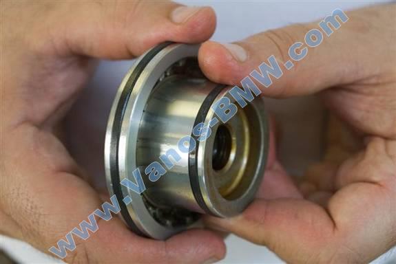
The vanos has two pistons with seals/O-rings. Each piston utilizes two seal/O-ring sizes to provide hydraulic sealing in two vanos cylinders of different sizes. Each piston also utilizes one further small O-ring. This O-ring mounts on a small cap that’s used to seal off a piston bearing. The OEM O-ring for this cap seems to also be made from Buna and is deteriorating in the same manner as the piston seal O-rings.
A vanos seals/O-rings repair kit can be acquired through Vanos-BMW.com, https://vanos-bmw.com/. It includes a vanos replacement set of OEM material Teflon seals and enhanced (Viton) O-rings.
Symptoms
Cars experience:
Overall loss of torque and power, particularly in the lower RPM range, < 3k. Bogging then surging at 3k RPM. Uneven power distribution and RPM transition. Engine hesitations in the lower RPM range, < 3k. Louder idle and intermittent idle RPM hiccups. Difficult takeoffs. Loss of power and bogging when AC on. Increased fuel consumption.
Repairing the vanos seals provides:
Overall increase in torque and power, particularly in the lower RPM range, < 3k. Resolution of bogging then surging at 3k RPM. Smooth even distribution of power and RPM transition. Resolution of engine hesitations in the lower RPM range, < 3k. Quiet stable idle. Smooth easy takeoffs. Improved performance when AC on. Reduced fuel consumption, by ~10%.
Cars with the M52TU engine (98/99-00) experience cold weather cold start idle jolts and possible stall.
In some cases the engine computer will generate a fault code. The code is usually associated with the vanos exhaust side. This is due to the powerful spring in the vanos exhaust cylinder which forces the piston out. Fault codes include:
P1520 (BMW 104, 0x68): B (exhaust) Camshaft Position Actuator (faulty reference value).
P1523 (BMW 106, 0x6A): B (exhaust) Camshaft Position Actuator Tight or Jammed (mechanically stuck).
P1397 (BMW 18, 0x12): Camshaft Position Sensor B (exhaust) Circuit.
The exhaust camshaft position sensor (CPS) is a common failure. But if replacing the exhaust CPS (w/ OEM CPS) doesn’t work then it’s likely the vanos failure.
On 01+ M54 & M56 engine cars codes P1520 & P1523 were removed. Thus code P1397 appears.
Diagnosis
With M52TU engine cars (98/99-00) with cold engine idle jolt symptoms, the vanos intake solenoid (metal cylinder) electrical connector can be removed. If the idle jolts cease then the problem is the vanos seals.
A vanos exhaust side fault code, as described above, is most likely a vanos seals failure indication.
Otherwise the vanos needs to be removed from the engine for inspection. Once the vanos cylinder covers are removed, an inspection of the piston seals fit in the cylinders will show a loose fit and thus a seals failure. Removal of the seals from the pistons will show the inner O-rings have flat spots and a loss of elasticity.
In general, a diagnosis is not necessary. The vanos Buna O-rings are deteriorating in 20k miles (32k kilometers). Thus essentially all the cars with this vanos have deteriorated O-rings and a failing vanos.
Repair Procedure
The following is an E46 & E39 double vanos piston seals R&R (remove and replace) procedure.
If the valve cover gaskets are over 40k miles (64k kilometers) old, then it’s prudent to replace them during this repair. If they are over 80k miles (128k kilometers) old, then it is a requirement to replace them during this repair, otherwise they might leak due to being dismounted and reused. These gaskets have an estimated lifespan of ~60k miles (96k kilometers) and replacing them during this repair requires no extra effort. The needed parts and replacement procedure are included as optional.
Repair time: 4 hours mechanic, 6+ hours DIY.
Parts, Tools, and Shop Supplies
Parts with part number pattern xx-xx-x-xxx-xxx are BMW parts and can be acquired from a BMW dealership.
Vanos-BMW.com only provides the vanos seals repair kit.
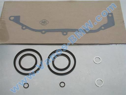
Double vanos seals repair kit (6-cyl) https://vanos-bmw.com/, vanos gasket (11-36-1-433-817) 6.73/each, 2 x vanos oil hose/pipe washer (32-41-1-093-596) $.25/each
Optional Parts
M52TU & M54:
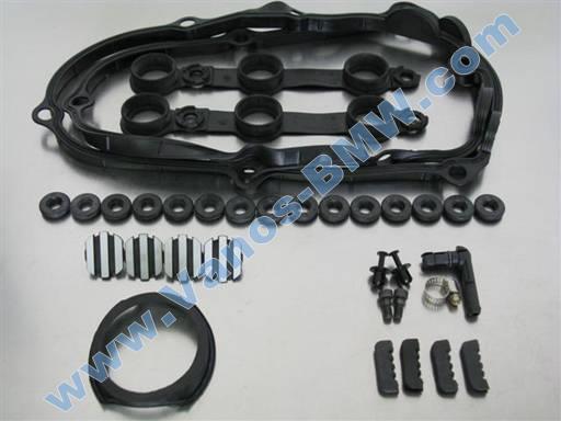
Valve cover gasket replacement parts: valve cover gasket set (< 09/02 11-12-9-070-990, >= 09/02 11-12-0-030-496) $34.26/each, 15 x valve cover bolt grommet (11-12-1-437-395) $1.73/each, oil fill neck gasket (11-12-7-526-447) 2.29/each
Easily breakable parts: 2 x vanos piston bolt (11-36-1-748-745) $1.42/each, 4 x engine cover bolt/nut cap (11-12-1-726-089) 3.27/each, (E39 2 x, E46 1 x) fan shroud rivet (17-11-1-712-963) $.27/each, E39: radiator overflow neck (17-11-0-419-132) $1.67/each
Easily lost parts: 4 x engine cover pad (11-12-1-730-352) $1.98/each
M56:
Valve cover gasket replacement parts: valve cover gasket set (11-12-7-521-009) $63.05/each & (11-12-7-521-010) $17.52/each, 15 x valve cover bolt grommet (11-12-1-437-395) $1.73/each
Easily breakable parts: 2 x vanos piston bolt (11-36-1-748-745) $1.42/each, fan shroud rivet (17-11-1-712-963) $.27/each
E39: Small adjustable hose clamp. Needed if radiator overflow hose OEM clamp not previously replaced with adjustable clamp.
Gasket scraper, putty-knife
Strait pick tool, razor knife, medium nose pliers (small, < 5”)
19mm combo wrench, Philips screwdriver (medium), 3 flathead screwdrivers (2 medium, 1 small), tack lifter, magnet pickup
13mm socket 1/2”, 3/8” to 1/2” socket adapter
13mm socket 3/8”, 11mm socket 3/8”, 10mm socket 3/8”, 8mm hex bit socket 3/8”
8 mm socket 1/4”, T30 torx bit socket 1/4”, T25 torx bit socket 1/4”, 3/8” to 1/4” socket adapter
1/2” ratchet, 3/8” ratchet, 1/4” ratchet, 3/8” long-arm ratchet
3/8” socket extension (short), 1/4” socket extension (short)
Torque wrench (8 Nm [6 ft-lb], 50 Nm [37 ft-lb])
Mechanical fan removal tools (not needed if electric fan):
32mm combo wrench, BMW water pump pulley holder (11-5-030) $20/each
Handheld sledge hammer (3lb)
Paper towels, water based cleaner (simple green 1:10), spray lubricant, brake cleaner, engine oil (synthetic 5W30)
Parts plate, small oil container, large cup
RTV sealant, magic marker
Not shown: large pad (quilt), oil pan, 3 small cloth towels, 2 grocery plastic bags
Repair
Car engine must be cold to perform repair procedure.
Right and Left denotations are from car front at hood orientation.
Removal of fan & shroud
E46 electric fan & shroud removal
E46 mechanical fan & shroud removal
E39 fan & shroud removal
Removal of cabin filter housing
E46 cabin filter housing removal
E39 cabin filter housing removal
Removal of valve cover
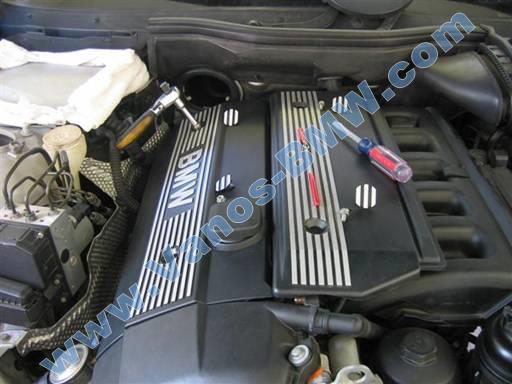
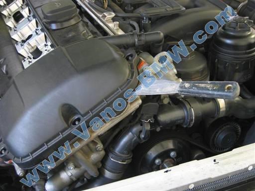
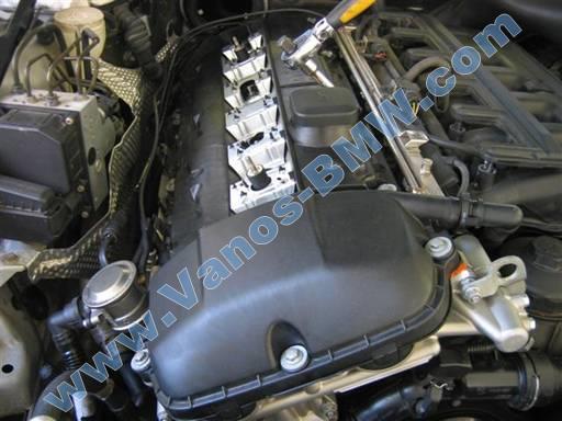
Remove engine top covers.
Pry off 2 center caps at each engine cover (flathead).
Unscrew 2 bolts at right cover, and 2 nuts at left cover (10mm socket 3/8” / 3/8” ratchet & extension, magnet pickup).
Remove right engine cover.
Unscrew oil fill cap, remove left engine cover, reinstall oil fill cap.
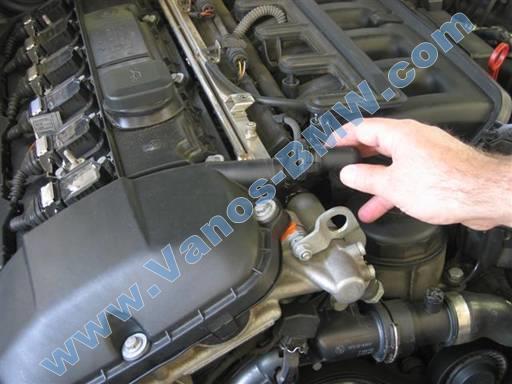
Remove valve cover vent hose at cover front right corner.
Press in hose connector ring clip at top and bottom and wiggle off connector.
Warning: Do not pull connector off. This can cause sudden release and break hose. Wiggle connector off.
New design (04+) O2 sensor fuel rail black bracket removal
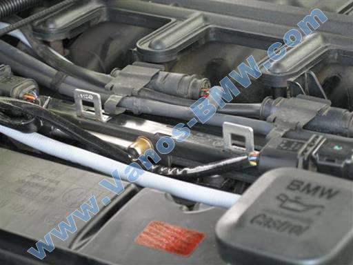
Remove 2 O2 sensor cable brackets at fuel rail.
Press down on O2 sensor cable bracket and pry out of fuel rail slot.
Remove O2 sensor black cable bracket at fuel rail.
Pry off bracket clips on side of bracket and remove bracket from fuel rail (small flathead).
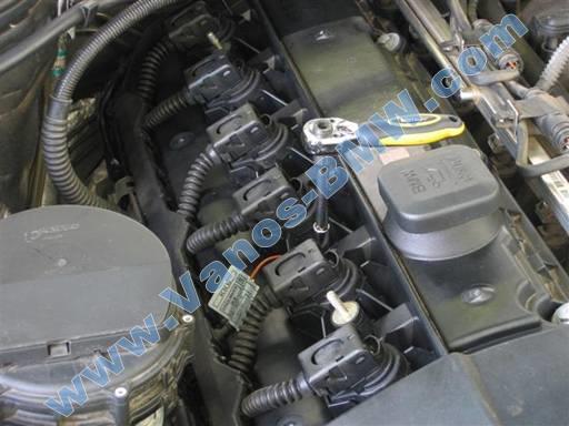
Old design coil / coil harness removal
Remove ignition coils electrical harness.
For each coil, pull up on coil connector metal lock and pull off cable electrical connector.
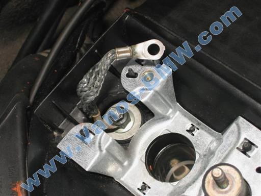
Remove coil harness ground wire from valve cover bolt/stud located between coils 2 & 3 (8mm socket 1/4” / 1/4” ratchet & extension, magnet pickup). Loosen cylinder 3 coil mounting bolts as needed to move coil to side to facilitate tool access.
Pry on each right side clip and pull out coil harness rail (flathead).
Pull off complete coil harness. E46: Set coil harness on intake manifold. E39: Set coil harness on strut tower.
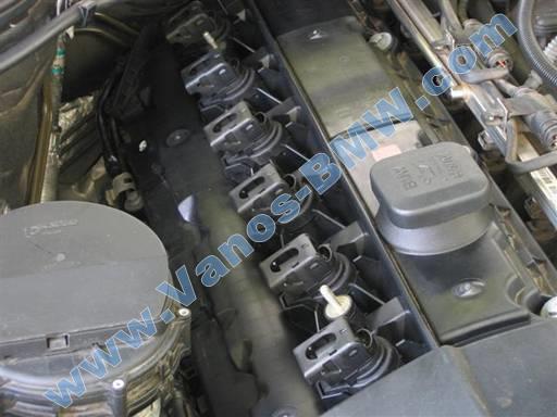
Remove coils.
Unscrew 2 mounting bolts w/ washers at each coil (10mm socket 3/8” / 3/8” ratchet & extension). Note coil ground straps at coil 1 & 6.
Pull up and out all coils.
Note: Maintain coil/cylinder association for reinstallation. This is not necessary, but is good practice.
Remove coil ground straps at Cylinders 1 & 6 (8mm socket 1/4” / 1/4” ratchet & extension).
New design coil / coil harness removal
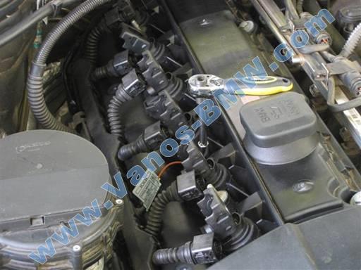
Remove ignition coils electrical harness.
For each coil, pull up and back on coil connector pivot lock until coil electric connector is thrust out and disconnected.
Remove coil harness ground wire from valve cover bolt/stud located between coils 2 & 3 (8mm socket 1/4” / 1/4” ratchet & extension, magnet pickup).
Note: Newest design coil harness has second ground wire between coils 4 & 5.
Disconnect coil harness rail from valve cover clips.
Pry on each right side clip and pull out coil harness rail (flathead).
Pull off complete coil harness. E46: Set on intake manifold. E39: Set on strut tower.
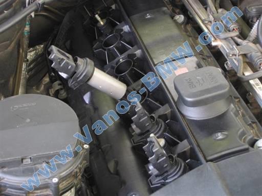
Remove coils. Pull up and out all coils.
Note: Maintain coil/cylinder association for reinstallation. This is not necessary, but is good practice.
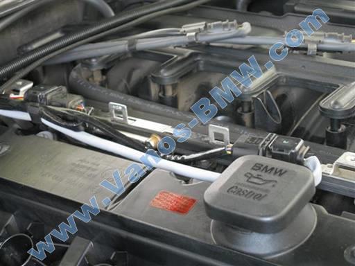
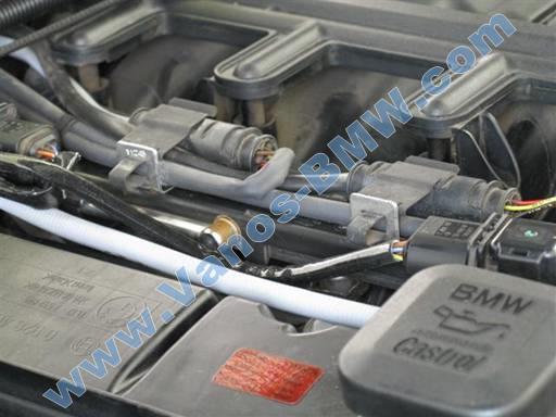
Remove pre-cat O2 sensor electrical connectors and cables, and secondary air valve vacuum hose, from exhaust side valve cover brackets and metal clip. Lift up on metal clip tab to allow cables to exit.
Remove electric boot and cables from valve cover rear left bracket and rear brackets.
Note: If silver metal cover present at rear left bracket, lift up on cover tab to allow removing electric boot and cables without removing cover.
Remove 11 valve cover mounting bolts w/ washers & grommets at perimeter of valve cover (10mm socket 3/8” / 3/8” ratchet & extension, flathead).
Note: Be sure to not miss the rear left corner bolt.
Remove 4 valve cover mounting bolts/studs w/ washers & grommets at center of valve cover (10mm socket 3/8” / 3/8” ratchet & extension, flathead).
Note: On older models (99), third bolt/stud from front is same as the perimeter bolts. This is due to no ground connection at this location. Note this for reinstallation.
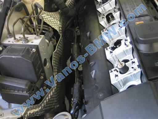
Remove valve cover from engine head.
Insert blade (putty-knife) between valve cover gasket and engine head at all front end accessible locations to break gasket bond. Be sure to break RTV sealant bond at sides of front half moon dips and vanos/head matting points on each front side.
Pull up and remove valve cover. If resistant, insert blade (putty-knife) between valve cover gasket and engine head at sticking locations.
Note: If valve cover can not be removed, double check valve cover 11 perimeter bolts and 4 center bolts/studs have been removed. If valve cover is stuck, pull up on free front end of cover and right side vent pipe neck to break gasket bond on remainder of valve cover.
Pull up rear left cover cables to allow cover removal clearance.
Maintain valve cover perimeter gasket with cover.
Valve cover perimeter gasket will stick at rear half moon dips due to RTV sealant. Pull up on gasket to release.
Remove valve cover sparkplug well gaskets from engine head.
Note: If gasket is stuck to engine head, attempt inserting blade between gasket and head from an edge (putty-knife). This facilitates gasket removal without breaking plasticized brittle gaskets into pieces.
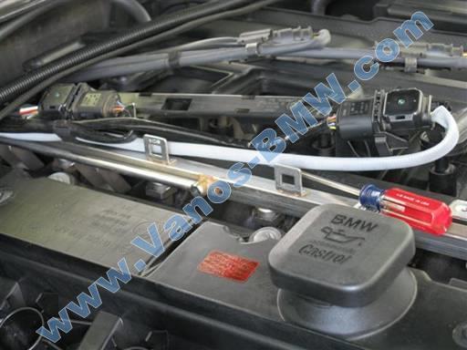
Removal of vanos
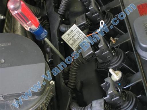
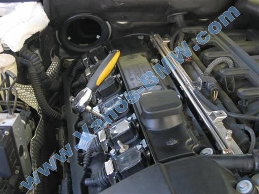
Remove vanos exhaust CPS (camshaft position sensor) electrical connector. Press in on side clips and pull off connector.
Note: If connector difficult to remove, pry out connector from end (tack lifter).
Remove vanos exhaust solenoid electrical connector. Press in on metal clip and pull off connector.
Remove thermostat electrical connector. Press in on metal clip and pull off connector.
Remove vanos intake solenoid electrical connector. Press in on metal clip and pull off connector.
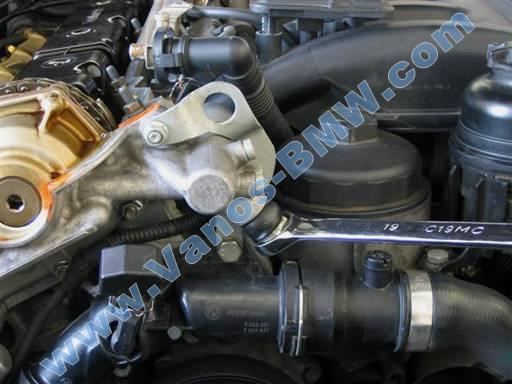
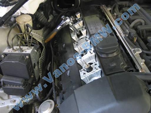
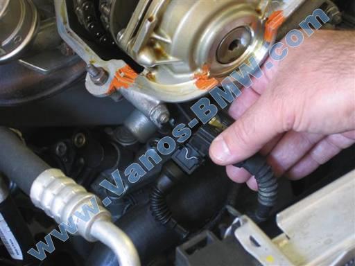
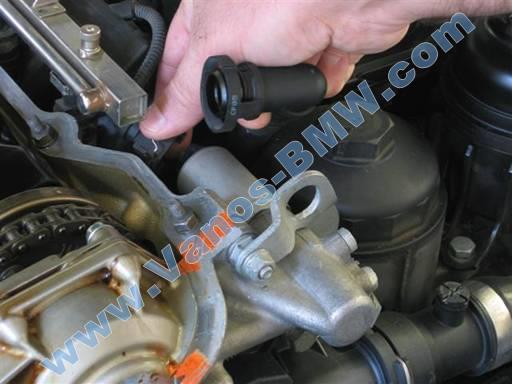
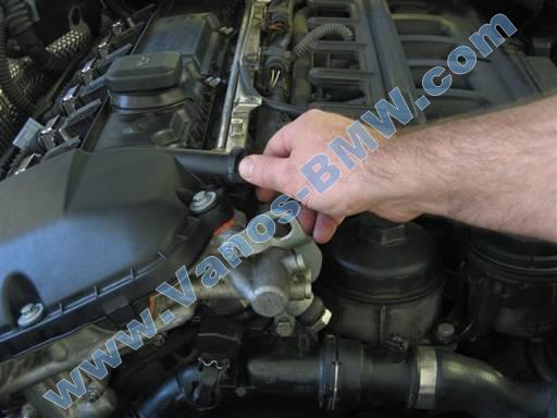
Remove vanos oil hose and bolt (19mm combo wrench).
Note: There are 2 washers, one at each side of hose end contact surfaces.
Discard washers.
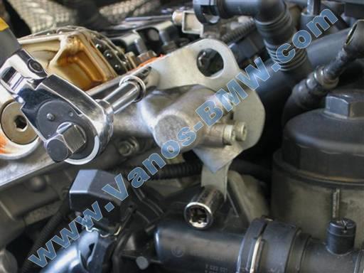
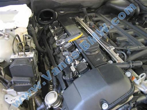
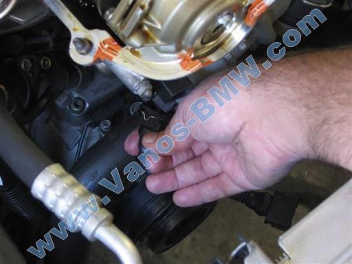
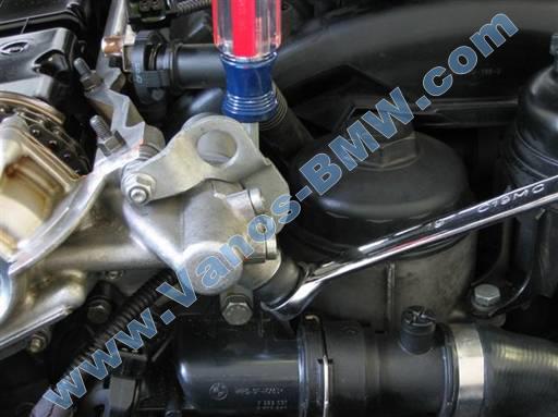
Remove engine lift bracket at vanos intake solenoid.
Remove top nut (11mm socket 3/8” / 3/8” ratchet & extension) and bottom bolt w/ washer (13mm socket 3/8” / 3/8” ratchet & extension).
Remove bracket. Rotate bracket bottom to top and then remove from top stud.
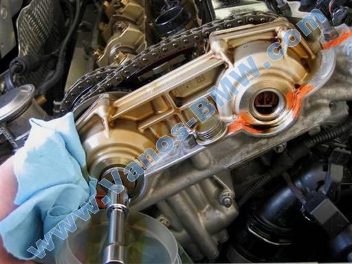
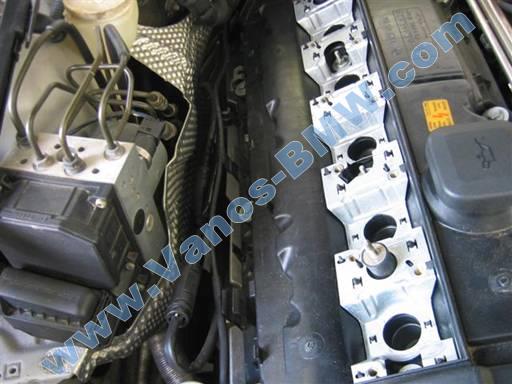
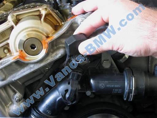
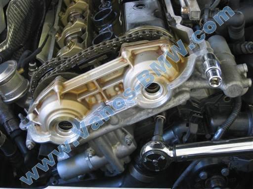
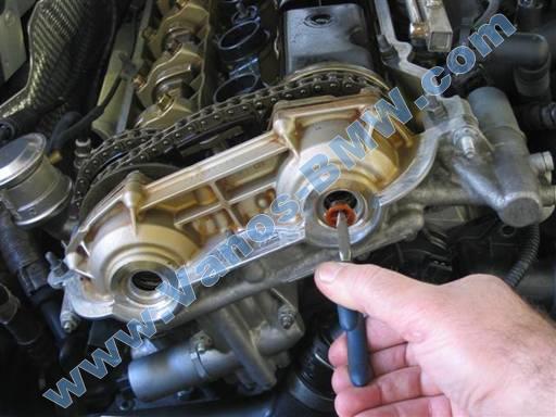
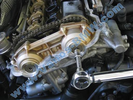
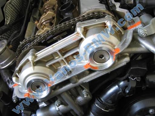
Remove 2 vanos cylinder front cover bolts w /washers.
Cover AC belt and lower radiator hose to protect from oil leakage (towels).
Initially break bolt seize (tough), then place oil container below bolt and unscrew bolt (8mm hex bit socket 3/8” / 3/8” long-arm ratchet & extension).
Engine oil will leak out from vanos cylinders. A significant amount will leak out from exhaust cylinder.
Stuff vanos cylinders with cloth to extract engine oil (towels).
Clean up oil spills, especially from belts and pulleys.
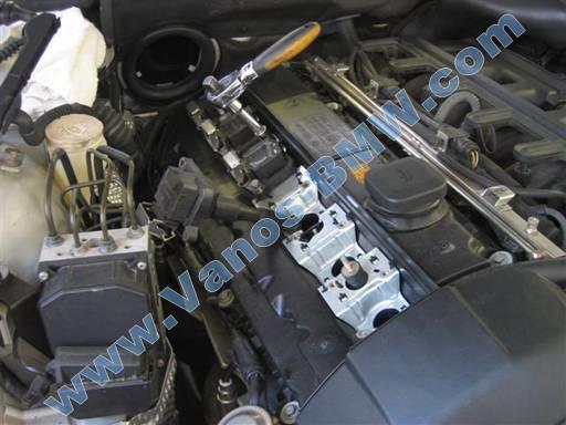
Remove 2 vanos piston caps (medium nose pliers).
Remove 2 vanos piston / splined shaft mounting bolts; left hand thread (T30 torx bit socket 1/4” / 1/4” ratchet & extension, magnet pickup).
Note: Make sure tool is perfectly perpendicular to bolt when first breaking seize. This helps prevent bolt head stripping.
Note: Bolt is left hand thread, thus unscrew by turning wrench from left to right (clockwise) (car front orientation).
Note: If a bolt breaks, continue removal of vanos from engine. Once vanos is removed remaining bolt in splined shaft can be easily unthreaded (pick tool), left hand thread.
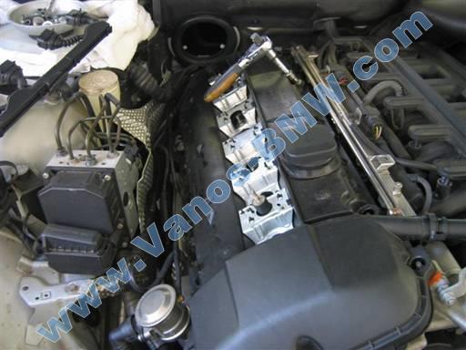
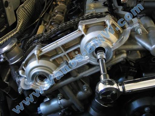
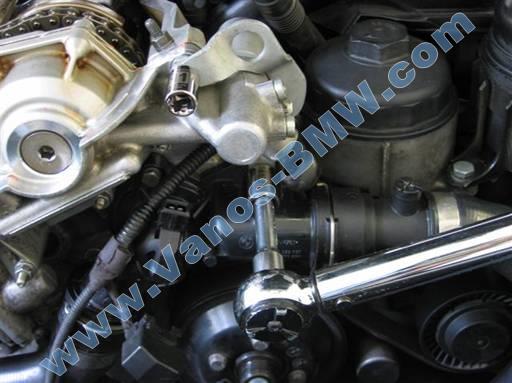
Remove vanos 6 mounting nuts at front lower half of vanos (10mm socket 3/8” / 3/8” ratchet & extension).
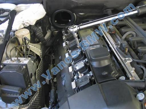
Remove vanos top right mounting bolt/stud (13mm socket 1/2” / 1/2” ratchet). Note: Deep socket needed (1/2”).
Pull vanos forward off head mounting studs and lift out of engine compartment.
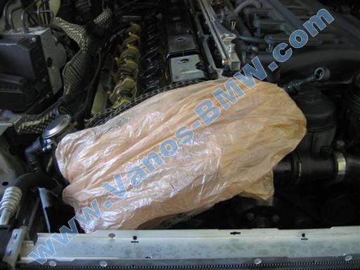
Note: Cover vanos with double plastic bags with towels at bottom to catch spilling engine oil (grocery plastic bags, towels).
Take vanos to oil receptacle and attempt to drain all oil from vanos (oil pan). Tilt vanos to facilitate drainage of oil from vanos cylinder covers, inner oil relieve spouts, and outer oil feed access.
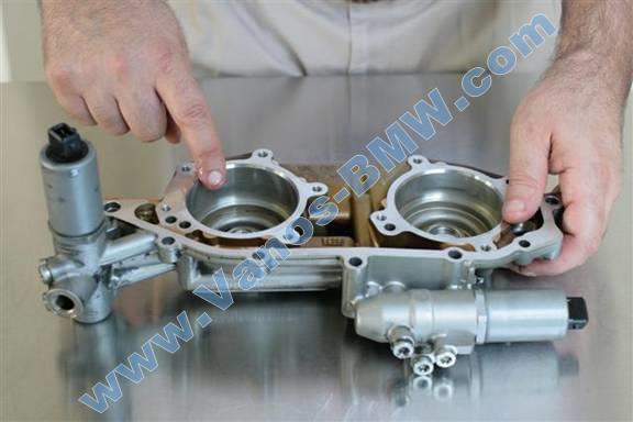
Lay vanos down on table with inner side facing up.
Remove and discard vanos gasket at engine head.
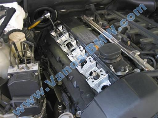
Replacement of vanos piston seals
During following seals installation procedure, great care should be taken to not drop and damage vanos components. Perform work over table, so if part is dropped it will fall to table top. Vanos cylinder cover gaskets should also not be bent.

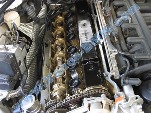
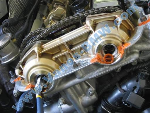
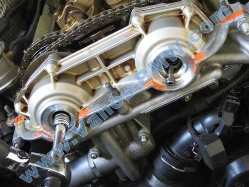
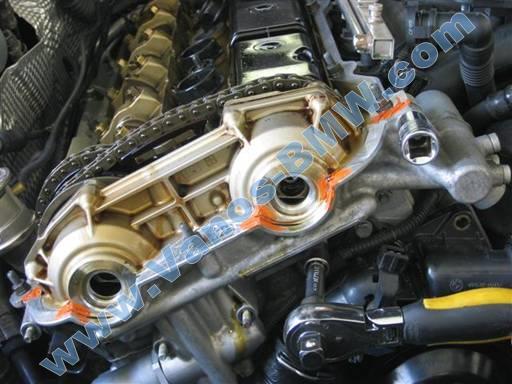
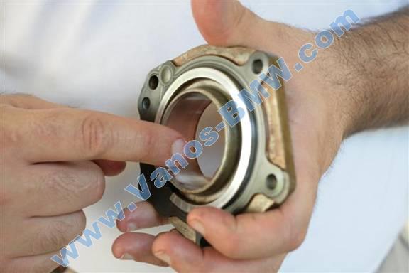
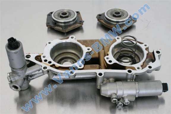
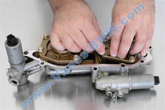
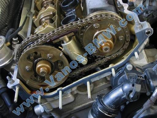
Note vanos intake and exhaust orientation (picture: intake left, exhaust right).
Mark (magic marker) an “I” and “E” on the vanos intake and exhaust pistons respectively to maintain piston to cylinder association. This is not necessary, but is good practice.
Note: Vanos intake and exhaust pistons are same part components and can be interchanged. Maintaining piston to cylinder association is good practice.
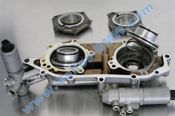
Remove vanos cylinder covers. Remove bolts at each cover (10mm socket 3/8” / 3/8” ratchet & extension). Initially break each bolt seize, then unscrew the bolts.
Note: Exhaust side cylinder has spring behind piston that will force cylinder cover off during removal. Push down on cover to facilitate bolt removal.
Remove pistons and exhaust side spring from vanos cylinders.
Drain oil from cylinders into oil receptacle (oil pan).
Wipe off oil from vanos components (towels).
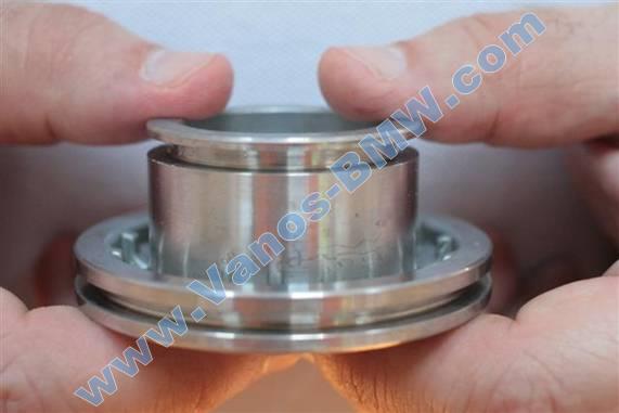
For diagnosis verification, insert pistons in/out of vanos cylinders (main body & covers) and note loose fit.
Inspect vanos cylinders (main body & covers) by feel for any marring. Walls should be exceedingly smooth with no felt irregularities.
Note: Seal sliding wear patterns will be present, and cylinder walls will not be as polished at ends of cylinders.
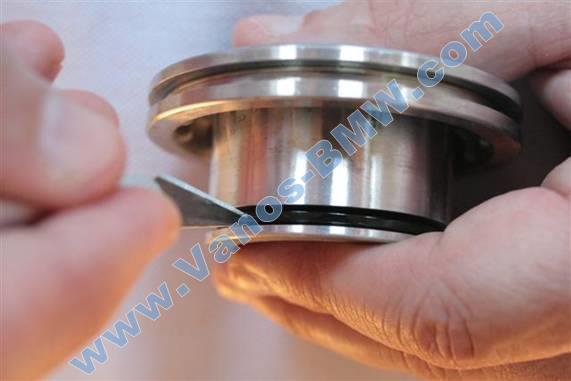
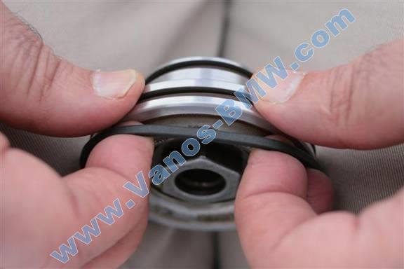
Piston seals removal
Two seal rings will be removed from each piston groove, total of four rings removed from each piston.
Note: During seals removal, care should be taken not to nick piston groove rims.
For each piston perform following seals removal.
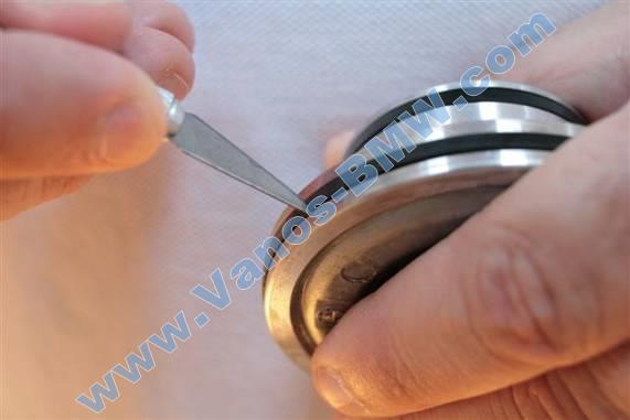
Cut cross section of piston large Teflon seal in piston groove (razor knife).
Note: Rocking of blade while pressing helps create cutting motion.
Remove cut Teflon seal from piston grove.
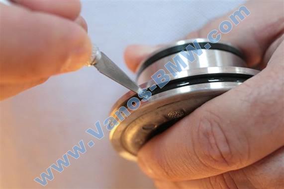
Cut cross section of piston large O-ring in piston groove (razor knife).
Note: Rocking of blade while pressing helps create cutting motion.
Remove cut O-ring from piston grove.
Cut cross section of piston small Teflon seal in piston groove (razor knife).
Note: Rocking of blade while pressing helps create cutting motion.
Remove cut Teflon seal from piston grove.
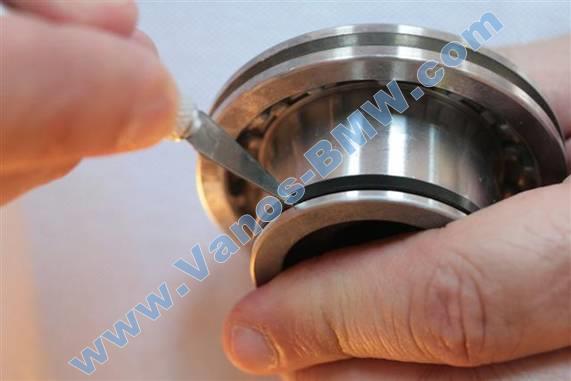
Cut cross section of piston small O-ring in piston groove (razor knife).
Note: Rocking of blade while pressing helps create cutting motion.
Remove cut O-ring from piston grove.
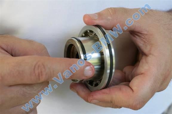
When seals removal is complete, piston grooves will have exposed metal with no seals.
Wipe clean piston grooves (towel).
Repeat seals removal for second piston.
Note: Deteriorated O-rings will be flattened at top and bottom surfaces, shrunk in size, and plasticized thus having a loss of elasticity. This is the common vanos failure mode.
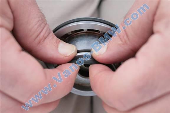
Piston seals installation
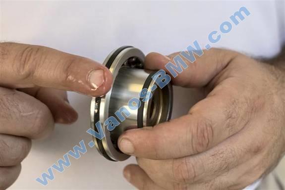
Before new seals installation, be sure four seal rings were removed from each piston, two from each groove, and piston grooves show exposed metal (above picture).
Two seal rings will be installed in each piston groove, total of four rings installed in each piston.
For each piston perform following seals installation.
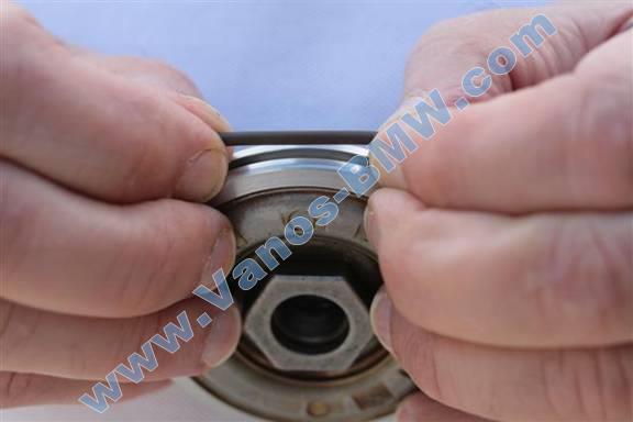
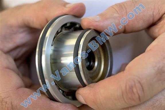
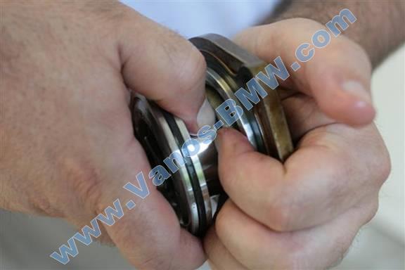
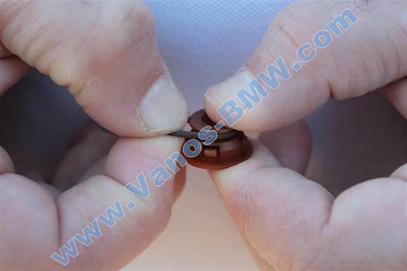
Install small and large O-rings (circular brown) in corresponding piston grooves.
Insert O-ring in corresponding piston groove at one end, and stretch other end over piston and drop into groove (hands/fingers).
Verify O-ring is not twisted in piston groove. Adjust and center as necessary (pick tool).
If Teflon seals in cold environment, < 70F (21C), soak seals in warm water for 2+ minutes.
Remove and dry Teflon seal just before installation.
Note: Perform following step on ground over large pad while kneeling with knees on pad. This minimizes risk of dropping piston and damaging its surfaces.
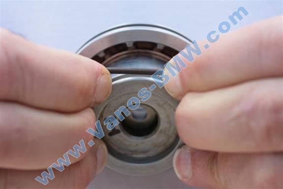
Install small and large Teflon seals (rectangular black) in corresponding piston grooves.
Insert Teflon seal in corresponding piston groove at one end, and stretch other end over piston and drop into groove (hands/fingers). Do not over stretch.
Note: Attempt to stretch Teflon seal evenly and take care to not scuff/damage. Some sliding of seal on piston rim is normal.
Note: Moderate force is needed to stretch Teflon seals.
Once stretched and installed, Teflon seals will fit loosely in piston grooves.
Repeat seals installation for second piston.
Piston Teflon seals resizing
For each piston perform the following seals resizing.
Apply coat of assembly lubricant (engine oil) to vanos intake cylinder wall. Be sure to include chamfer (rim bevel).
Apply coat of assembly lubricant (engine oil) to vanos piston large Teflon seal and adjacent piston surfaces.
Insert piston large end into intake cylinder at ~60 degree angle, then rotate piston to insert into cylinder.
Rotate piston to be flush with cylinder. As piston is rotated, excess seal protruding from piston groove will be collected and pressed into piston groove.
Note: Be sure to rotate lower piston end up, so seal does not bind at cylinder bottom edge.
If seal is binding, reposition piston and attempt again. With each attempt seal will partially resized. Eventually piston can be fully rotated without binding seal.
Insert piston fully into cylinder to properly position piston.
Allow piston to sit in cylinder for 2 minutes then remove. Teflon seal will be compressed close to original size.
Apply coat of assembly lubricant (engine oil) to vanos cover cylinder wall. Be sure to include chamfer (rim bevel).
Apply coat of assembly lubricant (engine oil) to vanos piston small Teflon seal and adjacent piston surfaces.
Insert piston small end into cover cylinder inboard side. Insert piston with a slight tilt to cylinder. Excess seal will protrude from groove at tilted out end of piston groove.
Press protruding seal into piston groove and rotate piston to insert into cover cylinder.
If seal is binding, reposition piston and attempt again. With each attempt seal will partially resized. Eventually piston can be fully rotated without binding seal.
Insert piston fully into cover cylinder to properly position piston.
Allow piston to sit in cylinder for 2 minutes then remove. Teflon seal will be compressed close to original size.
Verify piston Teflon seals have shrunk in size (resized) and recessed into piston grooves. Note: Teflon seals will protrude some (~1mm) from piston grooves.
Repeat Teflon seals resizing for second piston.
Apply coat of assembly lubricant (engine oil) to all four vanos cylinder walls. Be sure to include chamfer (rim bevel).
Clean vanos body / cover matting surfaces and all cover bolts (brake cleaner & towels).
Install pistons fully into vanos cover cylinders. Install intake/exhaust pistons (previously marked) into associated covers. Intake side cover has 5 bolt holes and exhaust side cover has 4 bolt holes.
Note: Some alignment and effort will be necessary to reinsert pistons into cover cylinders.
Insert spring in exhaust cylinder.
Install cylinder covers w/ pistons onto corresponding vanos cylinders.
On exhaust side, align spring to fit properly into vanos cylinder spring groove and piston spring groove.
Note: Intake side cover has 5 bolt holes and exhaust side cover has 4 bolt holes.
Note: Proper cover orientation can be achieved by aligning cover gasket oil access hole with vanos body oil access hole.
Note: Some alignment and effort will be necessary to reinsert pistons into cylinders.
Mount cover bolts (10mm socket 3/8” / 3/8” ratchet & extension).
Note: Exhaust side has resistance due to spring. Push down on cylinder cover while mounting bolts. Mount bolts evenly to insert piston evenly.
Fully tighten, 10 Nm (7 ft-lb) (10mm socket 3/8” / 3/8” torque wrench & extension).
Note: Tighten bolts evenly in crisscross pattern.
Double check piston movement in vanos cylinder by inserting piston in cylinder. Note: Exhaust side will need force to insert piston. Piston will spring out when force is released.
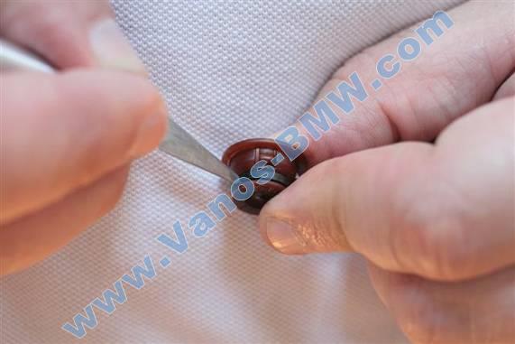
Remove 2 piston cap O-rings.
Cut cross section of cap O-ring in cap groove (razor knife).
Note: Rocking of blade while pressing helps create cutting motion.
Remove cut O-ring from cap.
Install 2 piston cap new O-rings (hands/fingers).
Note: O-ring should not be twisted during installation process.
Cleaning of parts
Note: When cleaning parts, spray cleaning compound on towel then wipe component with towel. Components can also be placed in a small container and sprayed with cleaning compound then individually wiped with towel.
Clean all mounting bolts/studs, nuts, washers, rubber grommets, ground strap ends (brake cleaner & towels)
Clean vanos matting surfaces; head, valve cover, oil feed (brake cleaner & towels).
Remove sealant compound on engine head; vanos joint and front and rear half moon corners (gasket scraper, finger nail).
Clean coils mounting contact surfaces (at coils) (brake cleaner & towels).
Remove valve cover gaskets from valve cover.
Remove sealant on valve cover gasket (pick tool, finger nail).
Clean valve cover gaskets (water based cleaner & towels).
Clean valve cover mating surfaces; at gaskets and bolt access holes (water based cleaner & towels).
Clean engine head matting surfaces; vanos, vanos studs, valve cover gaskets (brake cleaner & towels).
Mount clean valve cover gaskets on valve cover.
Optional: Replacement of valve cover gaskets
Remove valve cover gaskets from valve cover and install new gaskets on valve cover.
Remove 15 valve cover grommets from bolts/studs and install new grommets on bolts/studs.
Remove valve cover oil fill cap. Remove oil fill neck gasket and install new gasket. Mount valve cover oil fill cap.
Note: If oil fill neck gasket not present on valve cover, then gasket is likely of old design and can be fond on engine cover at oil fill hole. Remove old gasket from engine cover.
Note: If old gasket is stuck to valve cover, attempt inserting blade between gasket and cover starting from an edge (putty-knife). This facilitates gasket removal without breaking plasticized brittle gaskets into pieces.
Installation of vanos
Mount new vanos gasket onto engine head front. Mount top corners onto dowels and place gasket flush with head surface.
Note: Gasket is asymmetric.
Note: Fully insert vanos intake piston into vanos cylinder. This will simplify vanos mounting to engine head.
Mount vanos onto engine head front.
Insert vanos onto engine head studs, then vanos top corners onto head matting dowels. Fully insert vanos to mate flush with engine head.
Screw on 6 mounting nuts and 1 stud/bolt (top right corner), and tighten evenly working back and forth (10mm socket 3/8” / 3/8” ratchet w/ extension & 13mm socket 1/2” / 1/2” ratchet).
Fully tighten, 8 Nm (6 ft-lb) (10mm socket 3/8” & 13mm socket 1/2” w/ 3/8” to 1/2” socket adapter / 3/8” torque wrench & extension).
Note: Push vanos intake (right) piston from cylinder hole until it mates with splined shaft (finger).
Install 2 vanos piston / splined shaft mounting bolts; left hand thread (T30 torx bit socket 1/4” / 1/4” ratchet & extension).
Fully tighten, 8 Nm (6 ft-lb); left hand thread (T30 torx bit socket 1/4” w/ 3/8” to 1/4” socket adapter / 3/8” torque wrench & extension).
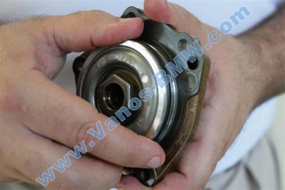
Install 2 vanos piston caps w/ new O-rings (medium nose pliers).
Apply light coat of engine oil to cap O-rings to ease installation.
Rotate cap to verify full insertion.
Install 2 vanos cylinder front cover bolts w/ washers (8mm hex bit socket 3/8” / 3/8” ratchet & extension).
Fully tighten, 50 Nm (37 ft-lb) (8mm hex bit socket 3/8” / 3/8” torque wrench & extension).
Note: Route electrical harness to engine side before mounting lift bracket.
Install engine lift bracket at vanos intake solenoid.
Insert bracket top hole onto engine top stud, then rotate bracket down to front of thermostat.
Mount top nut (11mm socket 3/8” / 3/8” ratchet & extension) and bottom bolt w/ washer (13mm socket 3/8” / 3/8” ratchet & extension).
Fully tighten, 10 Nm (7 Ft-lb) (11mm socket 3/8” & 13mm socket 3/8” / 3/8” torque wrench & extension)
Install vanos oil hose with bolt and 2 new washers (19mm combo wrench).
Mount first washer on bolt. Insert bolt through hose. Mount second washer on bolt. Screw bolt onto vanos.
Fully tighten, 32 Nm (24 ft-lb) (19mm combo wrench / by feel).
Note: Insert rod (flathead) between hose pipe and vanos intake solenoid to keep hose from turning.

Note: Route electrical cable for exhaust CPS sensor and exhaust solenoid behind vanos exhaust solenoid and valve. Insert cable section with minimal electrical tape between thermostat and vanos to route to rear.
Install vanos exhaust solenoid electrical connector.
Install vanos exhaust CPS sensor electrical connector.
Install Thermostat electrical connector.
Install vanos intake solenoid electrical connector.
Installation of valve cover
Place thin coat of RTV sealant at 2 engine vanos/head contact points, and at vanos/head front and rear half moon corners.
Allow sealant to solidify for 2 minutes before mounting valve cover.
Lift up on rear corner hoses and cables to allow cover to fit under them.
Install 11 bolts w/ washers & grommets at cover perimeter, and 4 bolts/studs w/ washers & grommets at cover center (10mm socket 3/8” / 3/8” ratchet & extension).
Tighten bolts/studs evenly working back and forth, assuring even pressure distribution on cover. Tighten until bolts/studs bottom out on head.
Fully tighten, 8Nm (6 ft-lb) (10mm socket 3/8” / 3/8” torque wrench & extension).
Install pre-cat O2 sensor electrical connectors and cables and secondary air valve vacuum hose at valve cover exhaust side brackets and metal clip.
Install cables and electric boot into valve cover rear left corner bracket. Align cables and hose into valve cover bracket and install electrical boot on top of cables.
Note: If silver metal cover present at rear left bracket, lift up on cover tab to allow installing cables and electric boot without removing cover.
Install cables into valve cover rear brackets.
Old design coil / coil harness installation
Install coil ground straps at Cylinder 1 & 6 (8mm socket 1/4” / 1/4” ratchet & extension).
Note: Ground strap highly bent end mounts on valve cover stud. Cylinder 1 strap connector orients to top corner, and cylinder 6 strap connector orients to bottom corner. This facilitates alignment of strap loose ends to coil bolt mounts.
Install each coil into original sparkplug well and mount with 2 bolts w/ washers (10mm socket 3/8” / 3/8” ratchet & extension). Mount ground straps with coil 1 & 6 bolts. Rotate between coil mounting bolts to mount coil evenly.
Note: Coil boot will not fully insert onto sparkplug during initial mount. This is normal.
Fully tighten, 10Nm (7 ft-lb) (10mm socket 3/8” / 3/8” torque wrench & extension).
Install ignition coil electrical harness.
Install coil harness rail on valve cover and clip into place.
For each coil, lift up on connector metal lock, press in cable electrical connector, and push down on connector metal lock.
Install coil harness ground wire on valve cover bolt/stud located between coils 2 & 3 (8mm socket 1/4” / 1/4” ratchet & extension). Loosen cylinder 3 coil mounting bolts as needed to move coil to side to facilitate tool access. Retighten cylinder 3 coil mounting bolts.
New design coil / coil harness installation
Install each coil into original sparkplug well.
For each coil, orient coil tab to align with valve cover coil mating bracket, insert coil boot into sparkplug well, and press coil onto valve cover until fully seated.
Install ignition coil electrical harness.
Install coil harness rail on valve cover and clip into place.
For each coil, lift up on connector pivot lock, press in cable electrical connector, and push down on connector pivot lock.
Install coil harness ground wire on valve cover bolt/stud located between coils 2 & 3 (8mm socket 1/4” / 1/4” ratchet & extension).
Note: Newest design coil harness has second ground wire between coils 4 & 5.
New design (04+) O2 sensor fuel rail black bracket installation
Install O2 sensor black cable bracket onto fuel rail.
Press bracket onto fuel rail until all clips snap into place.
Install 2 O2 sensor cable brackets onto fuel rail.
Insert cable bracket into fuel rail slot and press down and in cable bracket to fully install.
Install valve cover vent hose at cover front right corner. Push hose connector onto cover neck until it snaps on.
Install engine covers.
Install right side engine cover. Mount cover right side hooks under fuel distribution rail. Install cover 2 bolts (10mm socket 3/8” / 3/8” ratchet & extension, magnet pickup).
Unscrew oil fill cap, install left side engine cover, reinstall oil fill cap.
Note: Push down on rear left corner electric boot to achieve proper cover fit.
Install 2 nuts at left side cover (10mm socket 3/8” / 3/8” ratchet & extension, magnet pickup).
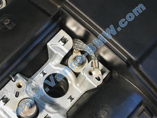
Clip on 2 bolt/nut cover caps at center of each engine cover.
Align silver lines on cap with cover. Insert clip at an angle and gently press down on other end (picture).
Note: Caps are dry, brittle, and will break easily.
Installation of cabin filter housing
E46 cabin filter housing installation
E39 cabin filter housing installation
Installation of fan & shroud
E46 electric fan & shroud installation
E46 mechanical fan & shroud installation
E39 fan & shroud installation
Post repair procedures
Allow RTV sealant to dry a minimum of one hour before driving car.
On first engine start after repair the engine can experience a couple engine hiccups at idle. This might be related to trapped air in the vanos.
Check and replenish engine oil.
Drive car, then park car and let engine oil settle.
Remove oil dipstick; wipe dipstick end; fully reinsert dipstick; remove dipstick again; read oil marking. If oil is low add needed (small) amount of new oil at oil fill cap at valve cover.
E39: Check and replenish coolant.
When car is fully cold (morning) open coolant expansion tank and check coolant level. Measuring sick top should be at expansion tank cap rim. Fill coolant as needed.
Drive car until warm. Slightly open each bleed screw and allow air to escape (Philips). Close bleed screw when only fluid is escaping. There is a bleed screw at the coolant expansion tank and a bleed screw at the radiator upper hose.
Repeat fill and bleed procedure as needed to achieve proper coolant level.
~200 miles (320 kilometers) of city driving is needed to fully break-in vanos seals and achieve optimum performance. Spirited driving will hasten break-in period. Initial improvements will be felt in the first few days of driving.