Installation manual DISA BMW repair kit
 |
Tools Required to complete this kit installation: 1. T40 Torx driver 2. Small flat blade (5/32) screw driver. 3. 5mm Allen (hex key) driver or wrench. 4. Small pair of diagonal cutters. 5. Optional – Small soft bristle stainless steel or brass wire brush. 6. Optional – Small 90 degree pick tool. |
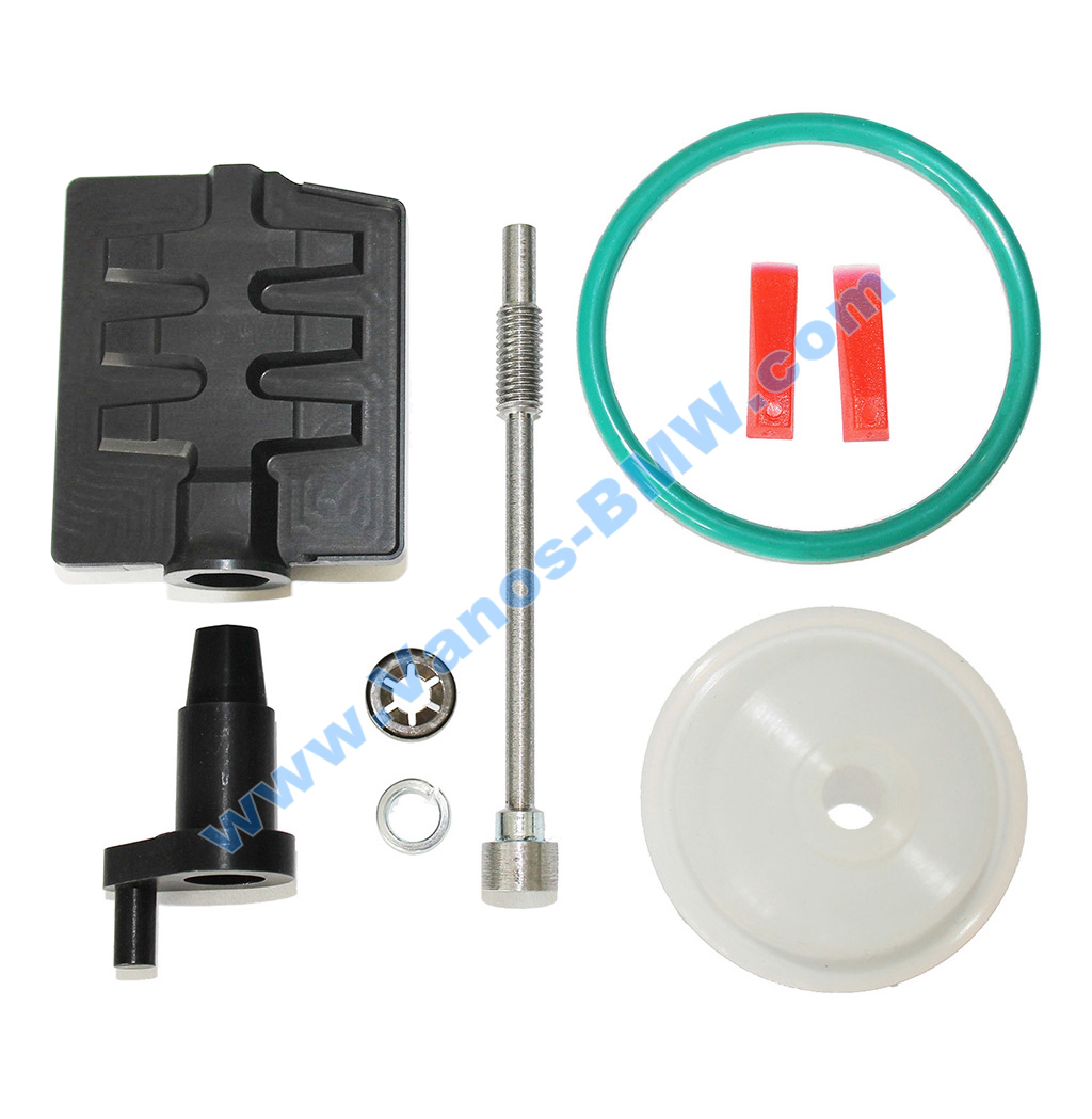 |
What comes in the kit: 1 Aluminum flapper valve. 1 Custom stell pivot screw. 1 Aluminum bell crank lever. 1 Green Viton O-ring seal. 1 5/16 Lag screw. 1 push on retaining clip. 2 plastic clips 1 silicone membrane for vacuum chamber |
 |
Start by removing the old DISA unit from the intake manifold by removing the two T40 Torx screws and one electrical connector securing the DISA. SLOWLY pull the DISA from the manifold. There is a steel pin in the end of the DISA housing (shown partially removed in the next picture) that can come loose and fall into the manifold during removal. Make sure that the pin is still in place on your DISA after removal. If not, Do not start the engine again until the pin is located. |
 |
Make sure that this pin is still in the DISA after removal. If not, it has probably fallen into the intake manifold as you removed the DISA. If the pin has fallen into the manifold it should be able to be easily retrieved through the DISA opening in the manifold. DO NOT proceed until you locate this pin. Note: The pin in this picture is show partially pulled out from its normal position. If your pin is still tightly seated into the flapper valve you will only see the flat head of the pin sitting flush with the end. |
 |
Before beginning the installation of the kit you will what to make sure that your DISA vacuum pot is in good working order. This is a very low failure item, but it’s always best to check it anyway. The test will confirm that your vacuum pot does not have a vacuum leak. The next step will tell you how to perform the test and what to look for. If your DISA flapper valve is worn & flops around loosely you will not be able to perform this test since closing the flapper valve will not move the vacuum pot lever. If this is the case with your DISA. This can be done after replacing the flapper valve. |
 |
To test the vacuum pot: 1. Manually close the flapper valve until it’s seated against the rubber seal inside the support frame. 2. Cover the hole shown with your thumb while valve is closed. 3. Release the flapper valve and see what happens. If your vacuum pot is good, the valve will spring open approximately what’s shown in the picture and stop. If the vacuum pot is bad the valve will spring open all the way. |
 |
The last thing to check before installing the kit is the frame and bearing boss. On rare occasions when there is extreme wear like what’s shown in the picture, the flapper valve can come completely loose from the part of the mechanism that controls its movement. If this happens the flapper valve can bend back and forth inside the intake manifold and damage or crack the upper bearing support. Clean around the area shown in the next picture and check for any signs of cracking. |
 |
Both vacuum pot and cracked bearing support failures are rare, but we would rather be sure that you are repairing a serviceable DISA and are happy with the finished results of the repair. If you’ve determined that your DISA valve is serviceable you can now proceed to the installation of the kit. |
 |
The installation begins by removing the actuator access cover. You’ll need a small flat blade screwdriver. Push in and pry up at the location shown. The cover pops off easily. |
 |
This is what’s under the cover. The creme colored piece is the bell crank lever which rotates the flapper valve. This is the piece that typically wears out and causes most of the problems. The black piece is the lever that connects the vacuum pot diaphragm to the bell crank lever. |
 |
Next you need to remove the retaining clip that holds the vacuum lever onto the bell crank lever. Work the clip off by prying up under clip with a small flat blade screwdriver. Alternate prying up on opposite sides of the clip until you have worked the clip off. There is a new clip in the kit so you don’t need to worry about damaging the stock one. |
 |
After removing the clip you can pop the vacuum lever off of the bell crank lever. Using a small flat blade screwdriver at the location shown, pry up the vacuum actuator lever until it pops off of the pin on the bell crank lever. If your unit is badly worn you may need to hold the creme colored bell crank lever in place so that it doesn’t try to lift up when prying up the vacuum lever. |
 |
To test the vacuum pot the alternate way, push the vacuum lever all the way in with your figure, then cover the hole, then release the lever while keeping the hole covered. If the vacuum pot is good the lever will spring back about half way then stop. If the vacuum pot is bad the lever will spring back all the way |
 |
Next you will be removing the bell crank lever from the housing. This can easily be accomplished with a pair of pliers. |
 |
If you have a badly worn DISA, you will probably be able to pull the bell crank lever out by hand. |
 |
The next step is to remove the pressed in steel pin. This is a critical procedure if your DISA is new or the pin is still fully seated in the flapper valve. The pin head is very thin and sits flush with the top of the support bearing, so there isn’t an easy way to grab it. You need to get a proper size screwdriver blade that just fits between the top edge of the flapper valve and the underside of the framework at the location shown. Position the blade so when you twist the screwdriver, it will pry up on the framework. A used DISA may have the pin already falling out. If you have one with the pin fully seated, be careful not to damage the framework. |
 |
This is what the pin head looks like after prying up on the framework. You need only pry enough to form a gap under the head. |
 |
Now you can remove the pin with a small pair of diagonal cutters. |
 |
Here is the steel pin removed. It’s pressed in pretty tightly on a new unit. This is what has ruined a few engines after it fell out and went through the intake runner and into the combustion chamber. |
 |
Once the steel pin has been removed, the flapper valve can be slid out of the DISA housing frame work. |
 |
Now that you have the DISA disassembled you will want to clean the DISA housing. I recommend using a full strength industrial cleaner. Note the little hole pointed to in the picture, this is the vacuum port that actuates the DISA. Gently clean the hole if necessary. Do not put sharp objects inside the hole, there is a vacuum diaphragm valve. |
 |
This is the beginning of the installation phase of the kit. The valve, bell crank lever, & steel screw are shipped assembled. Now is a good time to disassemble them. |
 |
The first part of assembly involves lubing and installing the new bell crank lever. Apply the grease to the inner lip of the bell crank seal. Spread it around inside the lip of the seal. Next apply some grease to the middle section of the bell crank lever as shown. Spread it around the outside and avoid the tapered hex shaped section |
 |
Note the rotational alignment of the bell crank lever as shown and insert the new lubed up lever into the DISA housing. Push the lever all the way in. |
 |
Push the lever all the way in as far as it will go. It should look like this and will probably have grease on the tapered hex section from pushing it through the bearing. While keeping the bell crank pushed in with your finger from the opposite side, completely clean the protruding hex taper with a clean cloth and solvent. |
 |
Next, with a clean finger, push the bell crank back down until it’s flush with the surface as shown. Be careful, the goal is to keep the tapered hex portion centered in the hole so that you don’t get any grease on the taper again. The seal will hold it centered in place once it’s pushed down. |
 |
Next we are going to be installing the new flapper valve. Now you can slide the new valve into place. This is the only orientation that will allow the valve to slide in due to it’s shape. It goes in from the side with the vacuum hole with the valve positioned as shown. It’s designed to be a precision fit so it needs to be straight in order to slide in. |
 |
View of the new flapper valve properly in place. Center the flapper to the opening in the top support bearing. |
 |
Next you will be pushing the bell crank lever into place. If you want you can temporarily replace the steel pin and hold it in with your finger while you push the bell crank lever into place. This is not necessary, but it helps to keep that end centered while working on the other. |
 |
You will need to position the flapper valve properly before pushing the bell crank lever into place. This is the position you want the flapper valve to be in, 90 degrees (perpendicular) to the support framework. You will need to hold the flapper valve in this position for the next step. |
 |
Next, make sure that the bell crank lever is still aligned like this and that the flapper valve is perpendicular to the support framework, then push the lever into place as far as it will go. |
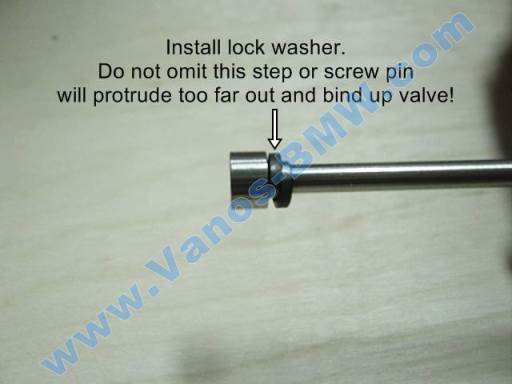 |
You will now prepare the new steel pivot screw for installation. Install the supplied lock washer onto the new pivot screw. Do not miss this step or the pin will protrude too far through the other end. The washer is there to provide a hardened surface between the screw head and the aluminum valve during tightening of the screw. |
 |
You can now install the pivot screw. Looking down the end of the support bearing hole will help with aligning the pin of the pivot screw with the hole. After lightly snugging the screw you will want to hold the flapper toward the closed position while fully tightening. This prevents you from applying tightening pressure to the DISA frame or mechanism. Tighten the screw with a 5mm Allen wrench or hex driver. You want the screw very tight to fully seat the tapered surfaces together. Once the screw is tight, make sure the valve will rotate back and forth without binding. Some resistance is normal due to the drag of the bearing seal, but the flapper should rotate smoothly from opened to closed. |
 |
You can now put the vacuum pot actuator lever back over the pin of the new bell crank lever and push the new retaining clip on. Use a socket or other similar tool to push the clip onto the pin. DO NOT push the clip on as far as it will go. Go slowly, you want the vacuum lever to have a little bit of vertical free play. If you push it on too far, pull it back a little with a pair of needle nose pliers while twisting the clip. |
 |
Double check that the flapper valve can be rotated to the closed position and back open without binding. If you manually close the valve, then release it, the valve should spring back to the fully open position, except as noted below. Note: The internal rubber boot of the vacuum pot has a tendency to kink when the valve is manually closed. This kinking may occasionally cause the valve to not spring back to the fully open position when manually closed and then released. This is normal and does not happen in the vehicle when the valve is actuated by vacuum. |
 |
You can now reinstall the plastic cover and you’re finished with the valve portion of the install. |
 |
Now that the new valve assembly is installed, all that is left is to replace the main housing seal. The M54 has the main seal molded into the framework which is why BMW doesn’t offer a replacement O-ring. The old seal needs to be scraped out. |
 |
The groove should look like this when you’re finished. Be careful not to scratch or gouge the groove. This can be a time consuming process if your molded seal is in good condition. If you are retrofitting a new DISA you can skip this step and keep the new O-ring for later replacement if needed. |
 |
Once the groove is cleaned you can install the new O-ring. Squeeze some of the supplied grease onto your fingers, then work the grease onto the surface of the O-ring before installation. This not only helps ease the reinstallation of the DISA housing into the intake manifold, but also aids in sealing. Wipe a film around the I.D. of the manifold opening as well. When re-installing the DISA housing into the intake manifold, push the housing in until the new O-ring contacts the manifold opening, then tighten the 2 torx screw finger tight, then tighten the screws 1 turn at a time with the wrench until they are tight. |
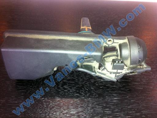 |
Exchange membrane vacuum chamber. |
 |
Open the cover of the vacuum chamber. Press the latches, lock them, pry the lid vacuum chamber with a screwdriver. |
 |
In the photo you can see the removed cover the vacuum chamber. |
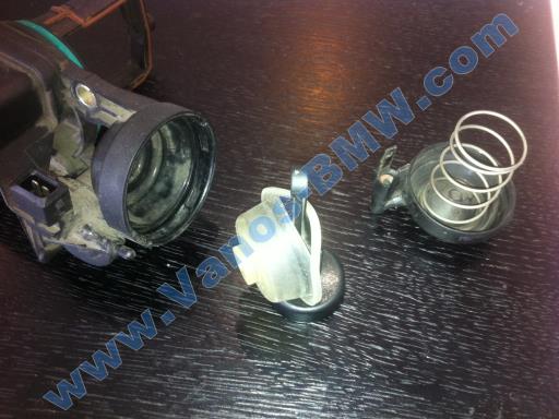 |
Remove the stem from the membrane. |
 |
Replace the membrane. Gently insert the rod into place and close the vacuum chamber (do not forget the spring). |
THE END |